Lps v5 output nano connector 5
Retest of daughter car 4.4.3v
4.3v
Its 5v at the LPS and 4.3 at the daughter card? What is the 5v at the nano end of the ribbon cable.
4.75v at the Nano end of ribbon, AND after a power off and back on, it is now 4.75 at the daughter card
We need to figure out why the sensor does not sink to gnd when it is not blocked. Can you take some pictures of the daughter board at different angles. What did the resistor on the diode side of the sensor read when you checked it?
Uggh! Nothing obvious. As soon as I get my machine back together I will verify that the uninterrupted signal should be less than 2.5v. Currentlyy machine is disassembled.
This AM I set up a TCST1030 sensor on a breadboard partly for my own sanity to see if it works like I expected. Luckily I bought one as a spare last week :).
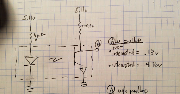
The sensor is mostly hooked up like the K40 although the collector resistor may be larger than is used on the K40’s Nano (shouldn’t matter).
As the attached video shows when the sensor is NOT blocked the output voltage is close to zero (.13V) as the receiver is full on. When it IS blocked it is close to the supply voltage or 4.76 because the receiver is almost off.
Note: the voltage when blocked does vary with the transitivity of the blocking material but in the K40 application that is a metal tab so its irrelevant.
missing/deleted image from Google+
My belief is that the sensor is NOT sinking to ground and as a result the sensor always looks like it is at home.
As @Vince_Lee suggests I think it might then try and pull back the carriage until it sees a change in the sensor which it does not.
The picture below outlines what the signals should be at the daughter card.
I suggest you test and document the points on the daughter card that the picture shows the values for, while your machine is powered on.
Careful not to short anything, you may need extra hands.
Turn power off and remove the daughter card.
Then reheat the connections in the RED box, they look suspicious to me. The should not be ball-like but flow into the joint like the other connections on the ribbon cable connectors.
Then measure the values again.
I do not know why the sensor if not turning full on but am convinced that it the problem.
Red box?
sorry I could not see the red box until I zoomed in
After re flowing the points, no change in the problem. The seller has agreed to send me a new Nano M2 board, Y step motor, ribbon cable, and Y end stop board. I don’t see how replacing all those can not resolve the problem. Mean time, I have found that after the machine powers on and locates the head in the middle of the machine, I can manually move the head to the correct approximate start location and make cuts from there. I just do not have a reliable repeatable zero location once the machine is turned off. Thank you all for the help as I struggle through this!
After you get the new parts and are working again, if you send the end stop daughter card and cable to me I will see if I can find the problem fix and return it to you. Dying to know what is wrong …I am still betting its not the controller.
@timb12957 it seems clear that the stepper is working so I would replace that last. You may want to replace the cable, end stop and controller all together so that if there is a controller problem it doesn’t blow up new end stops. Good luck…
Maybe I’m late but through all this have we swaped the X for the Y parts to confirm?


