An update on my spindle controller testing since I returned from vacation.

#OXSpindleDriver

An update on my spindle controller testing since I returned from vacation.
Here is a synopsis of the recent testing.

Created
… The schematic of the controller is complete and shared.

Verified:
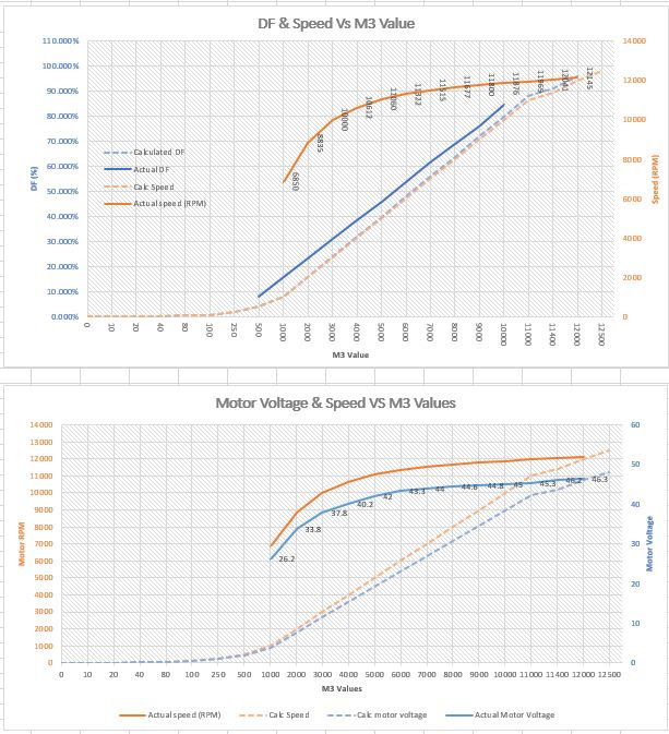
… The TinyG creates a PWM signal from M3 Svalues that are linear and impressively matches the calculated values.
… The TinyG PWM signal properly drives the opto-coupler in the controller
… The actual operation of the controller closely matches the schematic

Fixed
… The previous problem I had with the motor stopping at >95% DF was caused by the TinyG not outputting at values that are close to 500 rpm of the p1csh setting.
… My motor runs approx 12,000 rpm so I set p1csh to 13,000 and I can get a full 100% DF from the TinyG. My phase ccw settings are at 0 and 1.

Discovered
…The motor driver is not operating as I expected. Example: at 50% DF and with the PWM verified as correct at the drivers gate the motor is outputting 43 vdc, almost twice its correct value. This means that the range of control is from 26 vdc to 48 vdc about 1/2 its expected range. Therefore the speed is offset by almost 6x what it should be.
… No idea yet what the cause is so testing continues.

Questions
Not sure I still understand the phase settings p1cp(x). Apparently others are confused since I found a lot of discussion in various searches none of which provided a clear explanation of how they are used.
I gather that these values are the allowable low and high DF values that the TinyG will use when creating a PWM signal. Example: .2 and .9 settings will result in PWM values only between 20% and 90%. I also gather that the PWM will be linear-ized between these values? Correct…No? I did not test this theory.

More
More detailed content, schematics, pictures and test plans are here:

Your Question - “I gather that these values are the allowable low and high DF values that the TinyG will use when creating a PWM signal. Example: .2 and .9 settings will result in PWM values only between 20% and 90%. I also gather that the PWM will be linear-ized between these values? Correct…No? I did not test this theory.”

That is the way I understand to interface to operate as well

In my testing, I found that my controller+400W spindle did not reliably turn on below an input phase (DF) of 8%, and at that phase it turned at 5K rpm, so I set the low phase and speed accordingly. I did not find the spindle results to be surprising, they are rated for a max speed, no mention that they would be infinitely variable over the range from 0 rpm to max.

I’ll also comment that my results, and I assume yours, are “unloaded” phase vs RPM vs. spindle speed under working load. This then becomes a much more difficult discussion, since load on the spindle is affected by material, depth of cut, tool diameter, movement speed, etc.

Your Discovered comment: You report measuring 43Vdc at 50%DF. How are you measuring the 43Vdc? Measuring the DC component of a pulsed AC waveform requires a true RMS voltmeter.

Since your ultimate goal is to use the PWM signal to control a pulsed laser, I would expect you to get much more linear results measuring optical power vs phase(DF) with you settings of 0.0 and 1.0 for low/high phase. Are there reasonably price optical power meters now? They were pricey items in the 1990 time frame.

@cmcgrath5035
…My measurements are “Unloaded”.
…The DC voltage is measured with a DVM, I am not sure if it is a true RMS or not. However my problem is a much bigger error than would be created by not using a RMS meter. I am off by 6x. At 50% DF my voltage should be around 24vdc?

:slight_smile: I am not using this to control a laser (although I am working PWM improvements on my laser also in a different forum), I am using this for my OX 400W spindle.

I can see the problem clearly, the driver is malfunctioning, I just don’t yet know what is causing it, does’t make sense yet.

Note: If you did not try and calibrate this system you would not notice this offset as I can adjust between 6000-12000 rpm just not with rational PWM values from the TinyG. I know that lots of people are using the RioRand controller with the OX so either everyone has this problem or there is a unique condition in my setup.

Above you said: “In my testing, I found that my controller+400W spindle did not reliably turn on below an input phase (DF) of 8%, and at that phase it turned at 5K rpm”.
Shouldn’t 8% at max speed of 12,000 rpm be about: .08*12000 960rpm??? Are you using the RioRand controller/400W motor as well and having the same hidden problem?

Something is wrong!
See the scope trace below. The driver switches on during the high part of the gate voltage (PWM), switches off when PWM goes low and then for some reason switches back on in the middle of the low (off) part of the PWM signal. Dependent on the DF, sometimes it switches full on and at other DF it is partially on. This results in the motor drive being on for a large part of the cycle despite the PWM value. This behavior results in a non linear PWM vs speed because the PWM is only having a minor effect on the higher than expected average power to the motor.

I have tried two controllers and both do not misbehave this way on the bench at 24vdc using a small motor.

There is nothing in the trace that tells me why the driver is switching back on although the erroneous on periods seem to have more noise than the correct ones.

One controller behaves this way in the machine and I am going to test the other in the machine today. I expect it to act the same as I anticipate that there is something unique to the machine, its spindle motor current and/or running at 48vdc.

Stabbing in the dark
One possibility is that the gate is not being pulled hard enough to gnd as it has an unusually large pull down resistor (47K) and some high speed noise is turning it on.

Loosing some more hair!

4c9c8fad4fe24396bf30ea1d77667253.jpeg

“In my testing, I found that my controller+400W spindle did not reliably turn on below an input phase (DF) of 8%, and at that phase it turned at 5K rpm”.
[How did you force italics?)

I think your tests in the beginning showed that motor RPM is not linear across the full range D 0-1.0.
What I found was that DF=8% was the slowest I could reliably get the spindle to start up from “off” and run.
So I set Phase Low=8%, RPM low as 5000. I also determined that the spindle ran at 12K RPM at DF=95%, so set Phase High = 0.95 and RPM high = 12K. TinyG will linearize S values between 5K and 12K , mapped to settings between 8% and 95%

I can see you have a real oscilloscope, nice.
Can I assume the top trace is the output MOSFET gate and the bottom trace is likely the drain of that MOSFET? How do you have the grounds of your scope probes connected? I ask because it is not clear how “ground” and “earth” propagate thru the modern “buck” (transformerless) powersupplies we use these days, with respect to what was considered “ground” on a legacy style oscilloscope. That might be affecting your display.

I understand your “Stabbing in the dark” idea of inadequate gate pull down, but these are FETs so Gate current is ~0, so even high value pull down should be adequate.
You are using DC oscilloscope probes, correct?

@cmcgrath5035
The top trace is the gate of the MOSFET. So the high portions are turning on the MOSFET and the low turning it off.
The bottom trace is the Drain of the Mosfet. Low would mean the MOSFET is ON (grounded) and High would mean it is OFF (open).

The scope is grounded to internal DC supplies ground. The same as the MOSFET is referenced to, so I am sure it is displaying correctly.

The pull down phenomena I was referring to is that the gate voltage cannot float or it could possibly turn back on. At the time, I was trying to understand why the MOSFET is turning back on during the OFF portion of the PWM input.

You will notice in channel two during the on part of the PWM the MOSFET turns on and the trace goes to ground.
During the off state of the PWM the MOSFET turns off briefly but then turns back on … during the off cycle. There is nothing that suggests the gate is turning on the MOSFET at this time??

This is what causes the large error in speed. The motor is on for a large portion of the PWM period in spite of the PWM’s value. So PWM values effect only a small part of the off time.

That is why at all settings for S the voltage at the motor is way to high (6x) and the control is not linear.

Since my last update I have discovered through painstaking web research that MOSFETS can turn on from an internal feedback to the gate (dv/dt effect), especially when driving inductive loads. Best I can guess this is what is turning the MOSFET on during the PWM off cycle

I found these faults in the RioRand speed controllers operation:

…The design is sensitive to PWM frequency, does not operate properly and is unstable below a PWM frequency of <10,000 cps.

… When the controller is driven by 3.2 vdc it will work, but this low of voltage and drive allows the opto-coupler to operate in its non-linear region. Therefore voltage variations change the PWM period and in turn the motor speed. This is part of the source of error when being driven from TinyG.

The MOSFET drive is sensitive to motor load. It actually operates better when under load than when unloaded. Not sure I understand why but I would expect under load it will run closer to the programmed speed than measured unloaded.

The faults given above also causes the driver to drop out at low PWM DF values.


I have been working on modifying the RioRand controller to get to a better level of control. If this is successfully tested on the OX I may do a fresh design, depends on community interest :).

So far I have:
…Designed an open collector line driver to interface with the the opto-coupler properly from the TinyG
…Removed components not needed for a 48V only powered driver
…Bypassed the 555 timer
…DC coupled the MOSFETS gate drive
…Redesigned the optocouplers output to account for the inversion created by the line driver.
… Tuned the MOSFET-motor drivers output.

As you can see from a scope of bench tests, the modified drivers MOSFET switching is much more rational.

Google Photos

If you are interested here is a schematic of the “work in progress”. All suggestions appreciated!

https://www.digikey.com/schemeit/project/mods-to-rio-rand-motor-speed-controller-1-FRAM22G302TG/

@cmcgrath5035
You posted:
{
“In my testing, I found that my controller+400W spindle did not reliably turn on below an input phase (DF) of 8%, and at that phase it turned at 5K rpm”.
}
8% of 12000 rpm = 960 rpm not 5000 your off by 5.2:1 NO?
Are you using the RioRand also???

You posted:
{
[How did you force italics?)
}

Formatting text

To display text in bold, you would enclose it with the * character.

To display text in italics, you would enclose it with the _ character.

Last but not least, you can strike through text using the -character.

_ The MOSFET drive is sensitive to motor load. It actually operates better when under load than when unloaded. _
Well cool, hopefully the prior copy/paste is in italics.
If anyone else is interested, have a look at https://plus.google.com/+GplusExpertise/posts/9mfNTjFtPAm

My definition of ‘unloaded’ is motor connected, but free spinning with no load on the milling bit.
I am wondering if your definition of unloaded might have been motor not connected.
That would explain the weird waveform you show up a few lines, where the Driver appeared to be most-always on.
That waveform might be consistent with a capacitive only load from drain to Vspidle, which is what exists with no motor connected.

Oh well, italics did not work for me.

@cmcgrath5035 italics no spaces between the _and the word.

test

test two

@donkjr my definition of unloaded is with the motor connected and spinning with no load i.e. not cutting.
If it was unconnected there would be no waveform or at best a floating one as the drain is open :slight_smile:
You will notice on trace 2 it does turn off for a short period in the middle of the PWM period. If it was unconnected it would be a flat or floating line? It goes hard to gnd. Also in the modified design you see it behaving much better under the same conditions.

@cmcgrath5035 BINGO… .BingoBingo

Agreed, although you would still be modulating the Drain-Source impedance enough to perhaps see a transient effect of the Cap across the motor charging then discharging thru the flyback diode. That is why I asked.

You are operating at PWM frequencies I never tried. It has been a while since I experimented, I recall the noise emanating from the spindle to be obnoxious above 5kHz or so.
Most of the pwm controllers similar to this Rio Rand seem to operate in the 1-2khz range (the 555 freq).

For some reason, adding "_"s in front of, and behind a cut and paste did not seem to want to work.

@cmcgrath5035 I measured the internal PWM at a frequency= 2.55 KC.
On the scope when running from internal it has the same problem I have cited but since there is no reference (a pot) I doubt anyone realizes why it is running to fast.
With my mods the motor is actually more quiet and smooth even at 10 KC. I think that is because there isn’t a high frequency off-on error transition when the PWM period goes low.