Anyone done a manual moving table? not the motorized one,

Anyone done a manual moving table? not the motorized one, i´m looking for a cheap solution to quickly set the height without throwing $200 on it :slight_smile:

I would be happy with a table i can set with a hand crank. I´ll try to ask here before i try to make something myself :slight_smile:

I’m working on that project right now.
I don’t see need for active control of focus, at least not on this machine (maybe the next).
I’ve got several methods in mind. Here’s the direction I’m headed right now.

I’ve already gone to an air assist head which takes a 18mm lens, that’s a big improvement right there,.

I learned that the longer the focal distance, the wider the depth of field, or the “range” the beam is in focus.

I’ve gone to a 3" (76.2mm) lens, which puts my focus point right at the bottom edge of the rails. (so I can engrave on the top of a large flat object by bringing it up the the bottom of the rails.

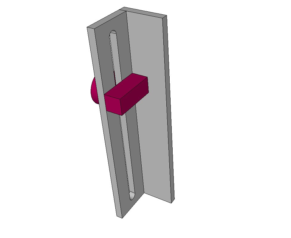
This morning I’m changing the support method for the rails to “hanging” from the internal sheet metal, and cutting away the bottom half of the cutting side of the enclosure. This will be done by using 1 x1" aluminum angle sections (4) one on each corner. The rear 2 will attach to the vertical part of the laser compartment wall, and the front 2 will attach to the front panel below the access door. The sections of 1/8" x 1" aluminum angle will be about 2" long with slots to allow use of 4 #10 machine screws. I am tapping the rails 10-32 and nutting the sheet metal connections.
The slots will allow full adjustment (vertically and horizontally) of the frame to get it properly aligned with the laser path.

This will allow me to raise a working deck up to the bottom of the factory “I” rails, and have no obstruction from the chassis sheetmetal. (this may be way farther than you wish to go, but it’s background on what and why I’m doing it)
A 3/4" Baltic Birch ply outer frame and removable left edge support panel will “cantilever” the enclosure on a 30gal wooden aquarium stand.

The mechanism to raise and lower the working deck will involve a panel with 4 corner holes, 4 1/4-20 sections of threaded rod, and 4 5mm bore 20tooth GT-2 pulleys tapped internally to 1/4-20. I have ordered 10 pcs 852mm GT-2belt. 2 idler pulleys and a drive pulley which will be run by a small dc motor (or hand crank)

The threaded rod sections will go in the old mounting holes in the bottom of the I rails, the panel (with cutout for screen as a working surface and 4 corner holes) will slide onto the 4 threaded rods, and be retained/adjusted by the threaded pulleys. The belt will encircle the pulleys, allowing them to be adjusted up and down precisely.
The belt will be tensioned by diverting a long span in the center forming a “T” shaped path, with the drive pulley at teh base of the “T”, and the idler pulleys at the intersection of the “T”. I may have to "split the belt drive into 2 sections or splice 2 belts into 1 with some kevlar thread. I may even order a longer belt if I can find a source for a 1+ meter loop.
You may be able to use a clothes dryer drum belt, or make/use something else as a belt/pully affair. That’s the real challenge to this plan. I’m also considering making a “climbing” deck that runs up and down 4 hanging GT-2 belt sections. If you come up with a better plan, I’d like to hear it. The more brains on a problem, the better…

I have some bearings I can inset into the deck if needed to smooth out operation, but I doubt it will be required.

I had to order 10 belts to get them in a closed circle. They only cost about 12 bucks for the 10, and I’d send you a couple if you intend to use a variation on my plan.

all you would really need past the belt is the pulleys, some hardware store all thread, and a plywood or mdf deck. It will be slow cranking, but you could use a cordless drill. I may just find s cheapie and make it a permanent part of the cutter. (I have an onboard 12v power supply I’m using for lighting and control power)

Hope this makes sense, and helps. I’ll post pictures if I ever figure out how to…

Scott

Awsome, thanks for sharing! Got my brain going a bit :slight_smile:
Hitting the hardware store to see what i can find!

Cool, let me know if you come up with a better plan. – back to work.

You are absolutely right, without autofocus, I can’t see a point to have motorized bed. the cheap manual method is more adapted to the K40 price range.

I keep envisioning a pop-up camper set-up, - you just put the crank in the front, and adjust it to where you want it.

Been hoping to run across something to re-purpose.

I’ll probably find something as soon as I get done rubegoldberging it. Always happens…

I keep looking at the gearboxes for the crank-out (casement or louvered type camper windows) - it’s gotta fit in the mix somewhere… they gear down, though, not UP which is what we need. Right size and get the corner turned, close…

My idea was something really basic, like bed on springs and you slot a piece of material (for thickness hight) in each corners. you can also imagine a little more complex meccanism for half the thickness. (focus in the middle of material)

I’m thinking about using this https://www.southernlabware.com/index.php/laboratory-support-jack.html?utm_source=google_shopping&gclid=CM6pmc3qossCFUI9gQod3joIDQ

It’s not perfect as I would have to take out the bed adjust the jack then put the table back in but for less than 50 dollars it might be a cheap z table

Also found the same thing on eBay for less than 30

What about a solution like this

One of theese in each corner, with a little knob to fasten it in wanted level. That moving piece have notches to my mostly used heights to make changes easy.
And fasten the bed on the moving part.
Or have a template to set the height before fastening the knob,
(example tepmplate, 24mm from the top = 3mm acrylic cutting).
The best thing, this can be made on the laser too.

Couldnt insert a image as a reply, so i put in a URL :wink:

I just made a poor mans attempt at a z table, it was a prototype made with Ply, 4" 8mm coach bolts roller skate bearings with an 8mm bore, 8mm threaded bar connectors and some nuts and epoxy. I drilled a pilot hole in the four corners. on 2 boards 18mm ply. on the bottom board i ressessed for the bearing plus another ressess to accomodated the dome of the underide of the bolt, so it could turn freely in the rebate. I connected the four bolts to the bearings epoxying them into place once i thought they were central. I then epoxyd them into the base. I then drilled 4 holes on the upper ply to accomodate for the 4 threaded bar connectors. i epoxied them into place. When all is dry I threaded each bolt throug each connector a bit at a time untill they were all protruding through the top. I then pur double nuts on the top and can use a socket to move the bolts. Anyway I am very pleased with makeshift attempt. I will try and provide a picture if anyone is interested.

I want to se pics, there is nothing like a poor mans solutions, there is only different levels of solutions :slight_smile:

If you make one for $5 or $500 doesnt matter, it solves your problem, all that matters :slight_smile:

I will take some photos saturday morning and post them. Its crude but it works fine enough for me. My version was all 6mm but will make a better version with 8mm. Im in the uk so dont know what time that will be for you.

I came up with a very economical concept which could be implemented a variety of ways, and is dirt cheap.

Ii should work equally well for someone who wants to cut out the enclosure floor or not.

The basic way it could be made is as follows.:

Basic Materials:

  1. ¼" straight wood dowel or equal, 16" minimum
  2. 2 pcs shaft collar to fit dowel (1/4”) Can use washers below if on a budget
  3. 6 or 8pcs flat washers to snugly fit the 1/4” dowel Ok to make from 1/8” ply.
  4. 2-3 meters Fishing line Powerpro (Spectra fiber) would be best, 50-150lb test. Kevlar artificial sinew or bootbinding thread will also work.
  5. 6pcs 10-24 machine screw eyebolts (available in Lowes, Home Depot, Ace etc)
  6. extra 10-24 nuts (for double nutting eyebolts)
  7. 4 matching eyes with wood screw tips (to attach to table)
  8. Moving floor of builders choice, with or without cutout. This must be self-guiding, with bushings in the corners or a similar method to keep it aligned. A cheap and easy setup would be a piece of ¾ mdf or plywood with holes drilled in it to fit the stock standoffs
    The principle here is for the dowel to be used as a pulley shaft, winding 4 individual lines in sync to raise/lower the table corners. The eyes are to be used as guides (in place of pulleys).

Build process (more or less):

A) Install the deck
B) Drill 2 aligned holes in the upper right corner of the cutting compartment, the 1st thru the front panel just below the joint of the 2 covers. The 2nd hole will be located straight back from the 1st and will penetrate the laser tube enclosure wall. (Be careful not to break your tube). This will give you a horizontal shaft, with the drive end facing the operator. Make sure to leave room for washers/collars. A small “L” clip could be attached to the right side wall(divider) and you won’t have to go near the Laser Tube with drill bits etc)
C) Insert the dowel thru the 1st wall, slip on the 1st shaft collar, 6 wood washers and the remaining shaft collar.
D) Slide the dowel just thru the 2nd wall (1/4” or so). Use the shaft collars to hold in in place, making sure to leave plenty of room between the laser tube and the end of the dowel. Create a handle or crank to turn he dowel.
E) Mount 4 machine screw eyes in the top corners of the I channel rails. (Eyes vertical with holes horiz).
Make sure the eyes and line path are clear of moving parts/laser path.

F) Once you determine the line routing etc, snug the eyes up, and run a line from from each corner of the table up and thru the corner eye (it need NOT go dead straight around the corner, that’s an advantage of the power pro, it’s very flexible, and won’t wear out fast) Rout the line to the end s of the dowel, the lines should share paths in pairs.

G) Use epoxy or thick CA and accelerator to attach the wooden washers, forming a “spool” for each line. Make it wide enough and aligned so that the line will tend to roll out in a single layer if possible. Each end of the dowel will have 3 wood washers creating 2 spools. Attach the line to a hole in the spool.

H) Wrap it up. Adjust so that the deck is level, check routing, create a crank and a brake of sorts to hold the setting. Common sense in effect.

With the 1/4” dowel, you should get about 3/4” of travel per turn (Pi X .25), which is a decent speed.

That’s my idea. Run with it if you like. Hope it helps someone, at least as a jumping off point…

Let me know how/if it works.

Scott

Just ran on this while doing something else entirely. Price is right, and you could run the jackscrew out the front…
http://www.ebay.com/itm/4-4-Lab-Lift-Lifting-Platforms-Stand-Rack-Scissor-Lab-Lifting-Stainless-steel-/121723155445?hash=item1c5743f3f5

@Scott_Marshall If you find one that is tight in the joints it may work, but if they have a slack of 0.5mm, it transfers to alot of millimeters at the edge of the table :slight_smile:
I tried making one from my kids LEGO, didnt work, the table shifted almost 10mm up/down ad the edges.

Let us know if you (or someone else) orders one and try it out :slight_smile:

I ordered one, I plan on using it for other things, already committed to my basic plan, bottom of enclosure is cut out and positioning rails are ‘slung’ from above.
The little adjustable table looks like I can use it for a setup I often use on my mill - to hold the tail of the workpiece. For the price, I’d bet your’re right about the play, but I’ll do a review when it arrives.

Maybe easy to fix the joints, then it may be a valid option to order :slight_smile:
Looking forward to the testing!

That’s a thought, maybe some nylon or brass bushings will tighten it up. Looks to be basic auto jack technology. I’m not sure what the INTENDED use really is. It’s a “lab lift” probably for glassware set-ups.
For 25 bucks I thought it’s a good 3rd hand for milling set-ups and that sort of thing. In the machining world, you don’t get much in the way of set-up tooling for that price. Adjustable fixtures can go into the thousands real fast, so I figure it’s worth a look.
Dues in on march 15-27th. We’ll see.