Anyone know how to adjust proximity sensors so they are less sensitive? Mine trigger whenever they are put on or near the machine or motor
If I were to hazard a guess, I would try a grounded cage/mesh around/between the object and the sensor. Mind you that is just a wild a$$ed guess. You might have to swap proximity sensors for something more contact related.
“Proximity sensor” is a bit of a large category. They generally come in magnetic, IR or capacitive form. So, what exact sensor do you have?
@Daid_Braam I have an NPN-normally closed inductive sensor (6v-30v)…one of the Chinese models-blue, Black & brown wires.
It seems like if you google the words damping capacitive sensors a lot of relevant links turn up. It is all in how you phrase things.
Do you have the polarity of the power for the sensor the right way round? If it’s triggering when mounted, it may be that you have the + and - reversed.
You say “Mine trigger whenever they are put on or near the machine or motor:” - that would indicate a wiring problem.
I’ve used these quite a bit, but not on my home machine, and they are fault-free. If I need to test one, I use a coin. I can bring the coin pretty close (<5mm) and it won’t trigger, but place one on top and it works immediately, without chatter.
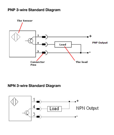
“When it comes to wiring a sensor, you can think of the “N” as standing for “Negative” and the “P” as standing for “Positive”. With respect to sensors, an NPN device is one that can switch the negative side of the circuit while a PNP device switches the positive side.”
Further… NC is the right choice, as you should have your sensors wired in series - any sensor triggering will open the circuit and trigger a fault.
The down side is that any fault in the sensor or cable will simulate triggering, will open the circuit and trigger a fault 
In my experience, earthing and shielding are key.
All your equipment - machine chassis, table/mount, motors, spindle, controller, PSU, sensors - should share a common ground. Ground loops are definitely something you want to avoid when mixing high (110/220v) and low (5v/12v/24v) circuits.
If you’re using inductive sensors, shielding sensor cables is a definite yes - especially where they may be in proximity of high-amp power cable, such as your steppers, spindle. If you have to have cables in proximity, try to avoid having them lie alongside - such as in the cable chain.
A good source of shielded cable for sensors is STP ethernet cable, suitably earthed. It’s cheap, but solid-core will break remarkably quickly if it is subject to moving - such as on your X-axis. Use quality braided STP suitable for patch panels, not the stuff used for infrastructure wiring, which is installed, tied down, and never moves.
THE BEST is to use optical cables with suitable electrical/optical transceivers, but its expensive and likely to be overkill for your situation - usually used when there is a lot of flux flying around that you can’t shield from, plus the investment needed in cable and tools is OTT for a single installation.
You will be experiencing one of two conditions: an installation that is faulty; an installation that is subject to noise.
Faulty is straightforward - check the polarity, check the earth. Interference is less straightforward, but there are some basic rules you can observe that will minimise the condition.
This covers most of them: https://www.controldesign.com/articles/2008/reducenoise0812/
It may end up that you need to mix sensors - simple microswitches for your Z-axis, for example, along with your inductive sensors for X and Y. The Chinese spindles are hella noisy, being AC and rotating at speed and it may be that a simple microswitch fixes that simply and easily, rather than having to spend a ton of time chasing something that’s always going to be problematic.
The 10x5 CNC router I occasionally use has the same NPN proximity sensors everywhere except the Z-axis and they are using a similar spindle to you - I assume for the same reason - you just can’t clean it up enough for a proximity sensor to work right.
EDIT: I forgot this:
Brown: Power Supply 10 to 30V DC-
Blue: Ground
Black: Signal Out
You want to check - your signal out will be the same voltage as supply in - you definitely don’t want to be feeding your sensor input too high a voltage or you will be needing a new controller sooner than the planned obsolescence period…
I would check at what voltage it really works - I have used those at 5V and they worked fine.
@Mike_Thornbury Thanks Mike,
I’ll check things out tomorrow.
Sorry for the multiple edits - I was looking for a sensor to wire up, but don’t have any to hand.
One of the most useful tools I’ve found when playing around is an adjustable bench power supply to simulate different situations. I have a permanent one on the electronics bench, but also a couple of portable units - one with an m/c battery, one with a switched PSU.
You don’t have to go crazy and buy a $2000 Fluke, a <$10 Chinese DIY one is just great for testing: https://www.aliexpress.com/item/DC-DC-Step-Down-Power-Supply-Adjustable-Module-With-LCD-Display-With-Case-GM/32727555852.html