Anyone know the min and max amperage for using the digital inputs on an Arduino?
I’m trying to have a setup for up to 4 inputs running at the same time, off a single line, and have it set up as a 3.74mA current. I’m wondering if that’ll be enough spread out on up to 4 inputs (using the current divider rule), but not overpowered for 1 input.
Normally Arduino digital inputs have virtually zero current, because, well, they’re inputs! When you use pinMode(pin, INPUT), the pin measures whether its voltage is high or low. Maybe you meant outputs? Your question makes little sense (at least to me) without context of the circuitry you’re connecting.
So basically, I’m needing to measure the inputs of up to 7 signals, only 4 of which can be active at any given time.
Since I’m taking 12v inputs, and sending them through Optoisolators, to keep the systems separate from the Arduino, I have a 5v feed coming off the arduino, going to each of the optoisolators. I figure that a 1500 ohm resistor dropping the current to 3.74 mA is good enough for 1 or 2 of the optoisolators working at any given time, but wondering about 4 of them.
Essentially, it’s like I’m using switches to feed the 5v to a few digital inputs, and am wondering what I should set the current to to to work with 1 or 4 signal input requirements.
I’m trying to feed them all off one line, to save space on a 2x3" board, but will still need to have diodes to branch off the digital input lines to the resistorized ground line.
I’m confused, can you share the schematic?

It won’t help, as I’m in the process of redoing the schematic for possible board production, so everything needs to be rewired.
But as you can see, the 4N25 optoisolators act as relays, being controlled by the 12v signal inputs.
All I need to know is what the min and max current ratings for the digital inputs are, so I can find a resistor that will make the setup work in the 2x3" available circuit board I have to work with.
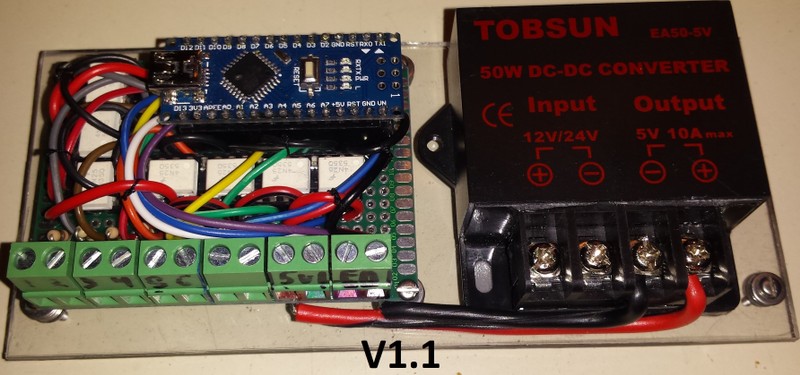
This is my footprint, so you can see why I’m trying to minimize the circuitry.
You should prototype this on a solderless breadboards BEFORE attempting a PCB layout. You should test with a voltmeter BEFORE connecting to Arduino or attempting even 1 line of code.
So much is wrong with the schematic. The unpleasant but honest truth is you’re a long way from anything even remotely likely to work (EDIT: in this schematic… apparently from later comments, some circuitry other than shown in this schematic has been built). Your only hope is solderless breadboarding and checking the voltages!
That schematic is a work in progress for a production layout, which was requested. I do not have, nor do I know if one actually exists, a macro with the capabilities of an Arduino setup, short of just the pin array layout.
The basic 4N25 circuit worked with a breadboard layout absolutely perfectly, and is essentially multiplied 7 times.
Everything works on the actual PCB: each 12v signal coming into the terminals gets dropped to 1.2ish volts to activate the LED in the 4N25. The 5.09v coming off the Arduino drops a bit passing throu the internal phototranny in the 4N25, where it gets sent over to the digital input pins on the arduino. Each one of those digital inputs is also connected to a 2N4007 diode, which all get connected to a single 1500 Ohm resistor.
It works perfectly (verified the 5.04 voltages at each of digital input pins on the arduino), I’m just wondering, again, what the minimum and maximum current ratings for the digital input pins are, so I don’t have to worry about replacing the arduino after a few minutes of testing, or having to solder a different resistor in place of the grounding 1500 ohm one.
The idea of “next to nothing” for current is great for theory, but I’m gonna need a number, especially if this design is supposed to be scrutinized by professional EEs.
I agree with Paul, that schematic is incomplete and does not help to understand your problem.
But to answer that specific question…
All I need to know is what the min and max current ratings for the digital inputs are…
Digital inputs are high impedance and typically draw currents in the microamp range. Digital inputs react to specific voltage levels NOT current !!
Maybe to understand the idea of “next to nothing” for current you can try a very simple test:
Connect +5V through a large resistor like 1Megohm to a digital pin and measure the voltage drop at the digital input, that will give you an idea of the equivalent resistive load within the device.
Thanks, so even splitting a 1mA available current 4 or 5 ways will be fine. Micro Amp works for me.
The reason why I was asking is because I need to run a bus bar for the grounding aspect of the digital input leads. Ideally, one would want to have each digital input ground connection resistorized, but for the limited amount of space I’m dealing with (area under the Arduino), I’m going with digital pins to diodes, then to a rail, slap a resistor on it, then ground it.
Actually, being curious myself, I did the exact test that I suggested on a UNO digital input.
I connected 5V through a 1Megohm resistor and measured 4.5 V at the digital input. So that means .5V drop on 1Megohm…
and since I = V/R…
The actual current sink is 0.5 microamps !!!
You say… so even splitting a 1mA available current 4 or 5 ways will be fine…
you are confusing me so much with that statement as the digital input WILL NOT sink any current !!!
Using the current divider rule, if I limit the available current, then I need to make sure that the available current will be able to push the 5v to 1 or up to 4 digital input pins. Voltage only works if there’s enough current to push it through… which is where that minimum current comes in.
Measuring the voltage at the Din is fine (checked and verified), but I want to make sure that there’s enough current there so the Arduino will understand that there’s in fact a signal there. Because if the inputs need a specific range, and I’m splitting that available current through x number of input pins, I want to make sure that each pin will have enough so that the Arduino understands that there’s a signal there.
The thing that reminded me of this issue goes back to one of our Signal and Systems labs, where we had plenty of voltage, but not enough current to actually get a signal response.
Taken to the extreme, the idea that 1ma would be enough current to provide signal inputs to 10000 arduino inputs is a bit ridiculous, leading to the question: “what would the necessary minimum input current actually need to be?”.
Just to be clear, you just need to ensure that the digital input pin gets close to 5V for a digital high and that it gets close to 0V for a digital low. I actually tried to find the electrical characteristics of the ATMEGA328p as found on the Arduino UNO and could not find it !!
In many digital devices the min that is still recognised a high is about 3.5V
For logical zero, it must have no more than 0.5V
Be careful, these number vary from device type to device type !
Voltage does not require current !!!
Just think of a fresh 9V battery, just sitting there by itself without any circuitry… for months even years… it STILL has 9V even if there is no current flowing !!!
With 10000 arduino inputs maybe you would need to start worrying about current but to my understanding you would be more concerned with the input capacitance that would greatly affect the switching waveform.
Many devices are capable of sourcing and sinking 20 ma on their digital output WHILE maintaining correct Output HIGH and output LOW voltages. So for a very slow switching circuit, you may actually get 10000 Arduinos to correctly read the slow signal !!!
Have fun trying it…
Just to be clear, the circuit works.
Ran it with several inputs on the terminals, and it works fine (at least the Pin 13 LED lights up using the sample button code, even when the last connection is the pin I chose to be read).
As for the circuit characteristics, I’m keeping the 3.33 mA as the max available current, so things seem to be working out nicely right now. Unfortunately, Din 5 and Din 9 work wonderfully, but D6,7,8,10, and 11 seem to have a lag in turning the LED off… maybe half a second. The circuits are identical, so I’m assuming it’s an Arduino Nano characteristic. This may or may not be a problem… not sure yet.
As far as having a voltage with no current, you must have both according to Ohm’s law. But in reality, to have a usable voltage, you must have some flow of electrons (the current). Having a high pressure water line requires there to be water, so with no available current , you get no potential voltage difference. Theoretically, figuring an air gap of 2 cm between the outlet holes, and a surface area of maybe 2 cm, the current flowing across an outlet at your house would be 7.76E-15 Amps, but essentially it’s zero.
@Ira_T - You have a knack for ambiguous & confusing language in describing your circuitry. Without an accurate schematic, this conversation is only a confusing mess. If you really want help, maybe you ought to put a little effort into drawing a complete and correct schematic for the sake of clearly communicating on the Internet?
If you really wish to ask only a narrow technical question about the (presumably AVR '328 chip - so much is unclear here we don’t even know exactly which Arduino board), all you have to do is refer to the datasheet. http://www.atmel.com/devices/atmega328p.aspx?tab=overview