Continuing my K40 conversion questions:
I have a digital Volt/Amper meter from eBay to show laser current and voltage. Am I right to connect the Voltmeter between FG and L- (GND) and Ampermeter between FG and Laser wire disconnected from FG?
Hmm. This seems scary to me. The ammeter seems like it might be fine since you’d be shunting it to ground which is what the built-in meter does (though I still wouldn’t be anywhere near it). I’m not sure about measuring voltage on the far side of the tube, however. You have a voltmeter that can handle 50kV?
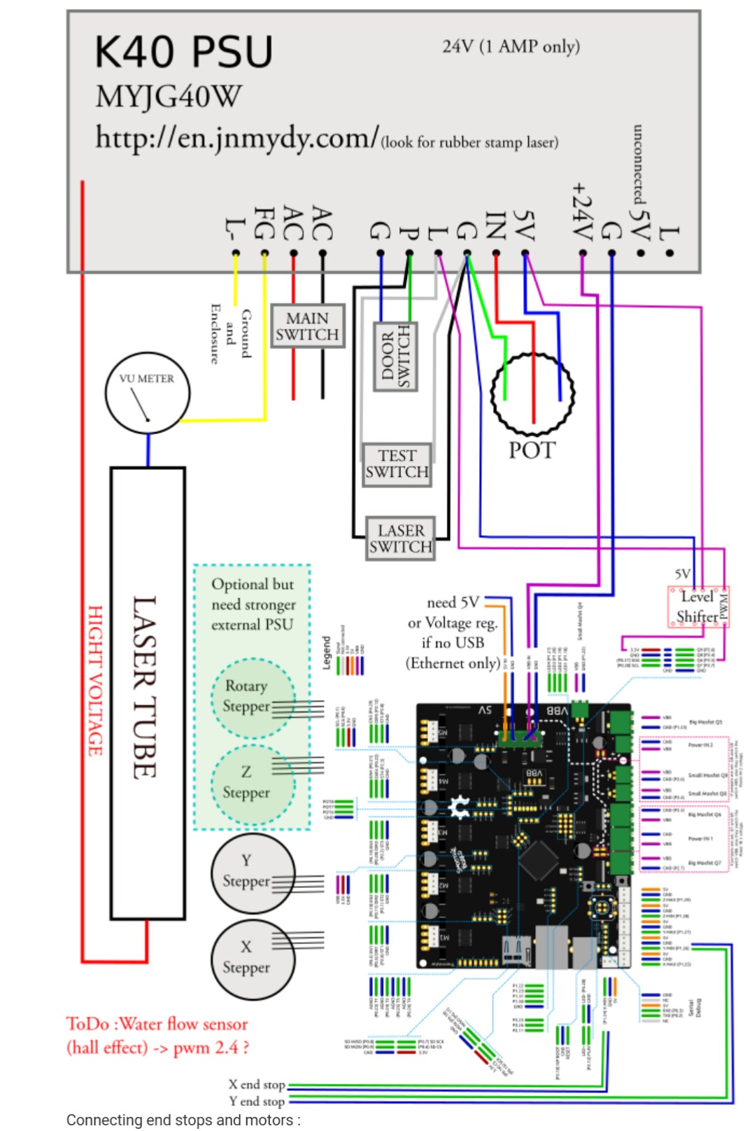
Ampermeter has to be connected in series, exactly as the VU Meter on the diagram, as current we want to measure must flow through it. But VU symbol in my opinion is related rather to Voltage (U letter is for Voltage and voltage unit is Volt) - that is the reason I got a little confused. Assuming VU is related to Ampermeter, diagram seems like OK.
Connecting Voltmeter between FG and L- (and not the far end of the laser tube) is just for displaying PSU OUT voltage reference. Possibly not really needed, but the voltage measure wire is already available in the digital voltmeter.
I don’t have an L- on my psu. The only reference I found for a psu with this pinout suggests that the negative return from the tube goes into L- and FG is instead for grounding the chassis. Dunno if yours is similar, but if so I don’t know what voltage one should expect between them