EDIT: Resolved
Swapped the PWM to pin 2.5, I guess my MOSFET must have went out. Also had to swap to M2 and M3 as the on-board drivers may have been damaged. Working well with no issues now
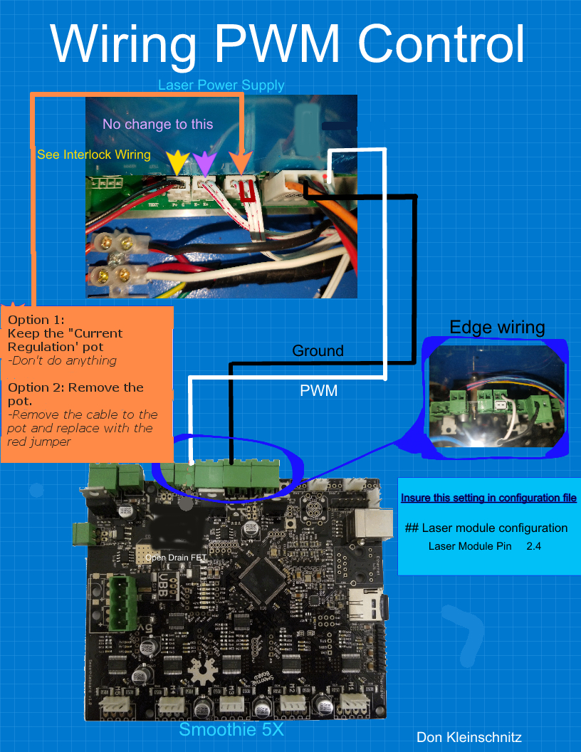
Still having issues with MY K40-S and Lw3/LW4 where the laser isn’tbeing fired through software. I had the machine running 100% in both LW3 and LW4, including qood greyscale results. The other day I booted everything up and updated firmware, etc. and now it wont fire from software. The test button on the LPS and the panel works fine. My interlock loop has an indicator LED similar to the one on Dons blog. Pot is still in the loop with the same small 3-wire voltmeter attached to show power setting. Config settings are:
Connections are smoothie edge connector on small mosfet connected to L on rightmost 4-pin connector.(this has never changed) with power - connected to gnd on same connector. IE:
24V
G - smoothie mosfet pwr1 -
5V
L - smoothie Q8 mosfet -
I know it can’t be a bad tube or LPS as it still fires fine if I cut out the controller. And the controller is still good as it can send a multi-part gcode job and run it as if it was lasering minus the actual pwn firing properly. Tried multiple config files, and both the old firmeare-cnc.bin, new one, and both old and new normal firmware.bin (renamed and cycled of course). Tried adding M3 and M5 to start and end gcodes, and as tool on/off, neither made a difference. No osc scope but used a multimeter to beep everything out and no shorts/breaks. Any ideas fellas? Smoothieboard 4xC. http://smoothieware.org/pinout
So the machine does everything properly from laserweb but never fires the laser.
You updated firmware but did not rewire anything.
1.) Is that correct?
2.) Try disconnecting the PWM signal that goes to L (I am assuming that is how it’s wired) and ground it with the Laser Switch enabled. Does that fire the laser?
couldn’t get the L to fire through a switch on the right conn, yet test button works on mid conn. Since I still need to swap a motor it seems a good time to pull the wires and re-verify.
Just to be sure your gounded the L pin that is the far right terminal and it did NOT fire.
The Laser Switch was engaged when you grounded that pin…
…is the above right.
…
If the above is true then something if wrong with the LPS control or the controls inside the LPS, not the smoothie or software as they are out of the circuit.
…
Can you pls post a picture of the LPS.
yea above is correct and i did swap a couple wires when i redid my control panel but bypassed all the changes with no luck. I’ll pull it apart and re-run it tomorrow after work. Im sure its something simple but boy can it be annoying. Note: an LED on the interlock loop wouldn’t mess it up would it? doesn’t seem to affect the test fire button.
in-line with interlocks so it has to be the gateway, and its the last thing before return to lps. but a 200ohm resistor on there as i needed a 160 but didnt have one.
i pretty much made a duplicate interlock board btw for a mental image with 6 blocks, main door- pwr door laser door -key sw on panel - led in/out. one big series loop.
@Domm434 the led may be your problem although I would expect that it would not allow the test button to work either.
You cannot put anything but switches between P+ and ground. P+ is not connected to 5V its actually the cathode of an opto-couplers LED. The current in that circuit cannot be limited.
See sketch below and how the ALARM LED is outside the interlock loops circuit.
Try just shorting out P+ to G at the LPS, engage Laser Switch and then ground L. Does it fire?
Did I miss a a picture of your LPS? That will help …
ahh so run the led off 5v and tie the gnd to the circuit, makes sense. And no haven’t put up a pic yet, feeling more and more like that one wire change so for now i’ll hide images of my shame
So after reviewing it today I noticed that the PWM(L) signal to smoothie is being constantly connected to gnd through edge conn on 2.4. Would this happen if there was a bad MOSFET? I can try swapping it to 2.5 to see if that fixes it. currently wired as pictured below(- contacts), and had it working in this setup for a while.
dunno but 2.4 was connected to gnd according to my multimeter continuity test so im assuming that MOSFET got torched. And after replacing my 12v high inductance stepper on x (rookie mistake) the new one is whisper quiet and waay smoother.