Hi.
I recently bought smoothieboard v1.0a X4 to move from Arduino (Mega, old but working, hacked to support 24V).
Hardware that I have:
- Smoothieboard x4 v1.0a
- 24V power supply
- 3 motors 42byghm809 (1.7A(u) 0.9deg/stp) for x,y,z
- 1 motor kh4234890006 (1.2A 1.8deg/stp) for extruder
- 24V 8A heat Bed
- 24V 3A hotend
- 3 bare endstops
- 2 temp reader
What I have done:
0. check cli connectivity over usb
- upgrade firmware
- make conf file for my delta (wiring do not allows me to plug X tower cable to M1, so I decided to switch pins in config file with extruder).
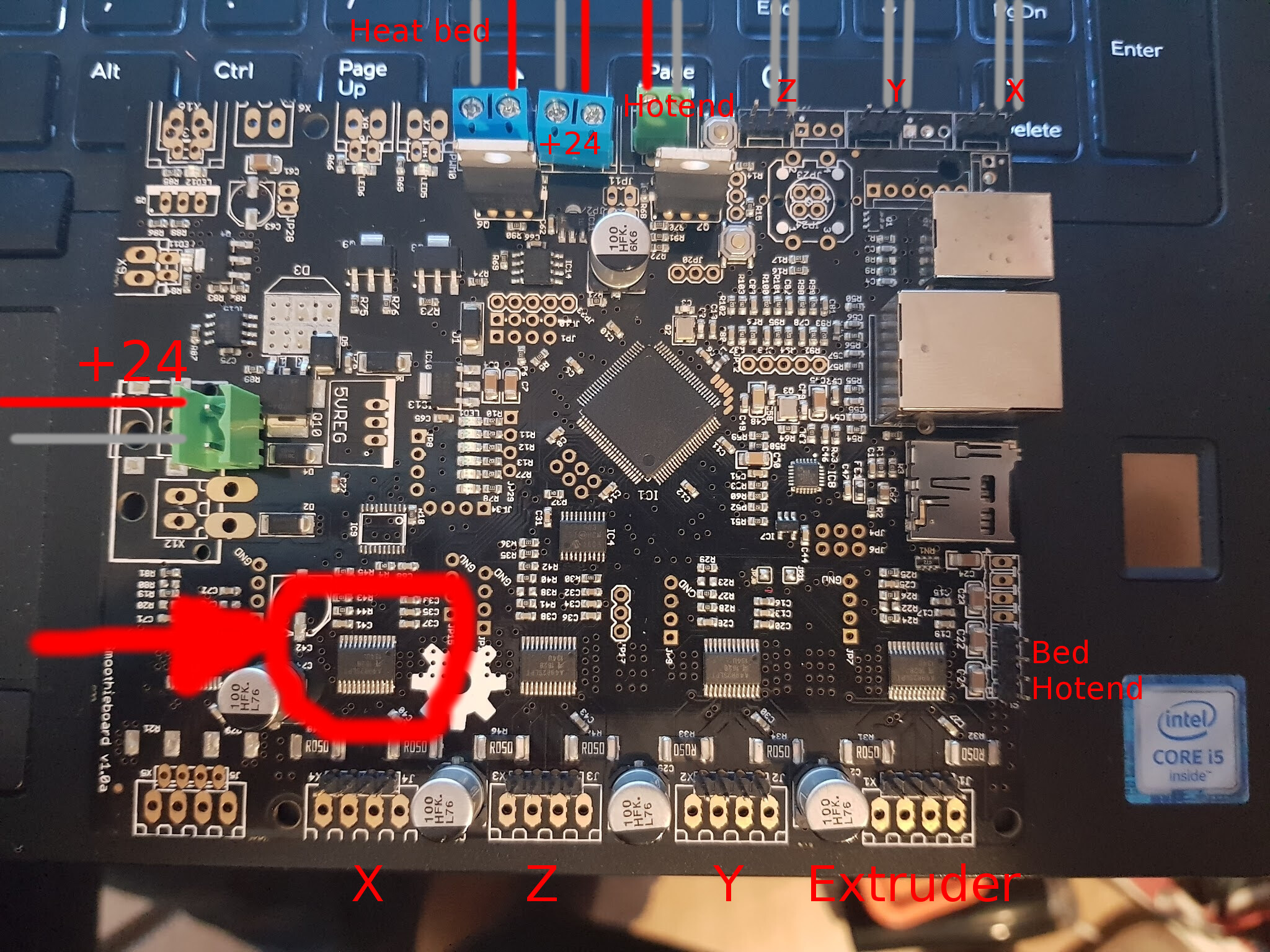
- wire things up (screen attached)
- check temp reads, endstops (without 24V PSU on)
- power on 24 power supply
- move X 10mm to right (nothing happens)
- turn off all power (when I touch board to unplug power it was hot at a4982 driver responsible for X movement - marked on attached screen).
- unplug everything
- after fev min turn board on over usb only to check damages
What newer was tested
- Heaters
What is still working:
- led (1-5 where 2 and 3 blinks - looks promising)
- cli connectivity over USB
- temp reads and endstop reads are correct
What is the problem:
- stepper driver responsible for X movement (marked on attached screen) gets hot even on USB cable
- there is no SD card mounted properly on board (SD card is visible and working over PC adapter), cli log:
> ls
sd/
> pwd
/
> cd /sd/
Could not open directory /sd/
> ls /sd/
Could not open directory /sd/
Questions:
- Is there any debug mode for board or any POST logs?
- I want to replace stepper driver, what else from power section I need to replace to get rid of powering stepper driver over USB ?
- I tried to wipe sd card, format with FAT32, place new firmware on it and re-flash firmware - without success. Board powers on, but SD is unreadable.
- Does my config file have any mistakes (maybe to high amps for a4982 drivers)?
- Did I wire board correctly ?
Thank you for any help.
My config:
# Smoothieboard configuration file, # NOTE Lines must not exceed 132 characters, and '#' characters mean what follows is ignored ## Robot module configurations : general handling of movement G-codes and slicing into movesBasic motion configuration
default_feed_rate 4000 # Default speed (mm/minute) for G1/G2/G3 moves
default_seek_rate 4000 # Default speed (mm/minute) for G0 moves
mm_per_arc_segment 0.0 # Fixed length for line segments that divide arcs, 0 to disable
#mm_per_line_segment 5 # Cut lines into segments this size
mm_max_arc_error 0.01 # The maximum error for line segments that divide arcs 0 to disable
# note it is invalid for both the above be 0
# if both are used, will use largest segment length based on radius
delta_segments_per_second 100 # For deltas only, number of segments per second, set to 0 to disable
# and use mm_per_line_segmentArm solution configuration : Cartesian robot. Translates mm positions into stepper positions
See
alpha_steps_per_mm 200 # Steps per mm for alpha ( X ) stepper and tower
beta_steps_per_mm 200 # Steps per mm for beta ( Y ) stepper and tower
gamma_steps_per_mm 200 # Steps per mm for gamma ( Z ) stepper and towerDelta configuration
See
arm_solution linear_delta # Selects the linear delta arm solution
arm_length 355.0 # This is the length of an arm from hinge to hinge
arm_radius 180.55 # This is the horizontal distance from hinge to hinge when the effector is centeredPlanner module configuration : Look-ahead and acceleration configuration
See
acceleration 3000 # Acceleration in mm/second/second.
#z_acceleration 500 # Acceleration for Z only moves in mm/s^2, 0 uses acceleration which is the default. DO NOT SET ON A DELTA
junction_deviation 0.05 # See
#z_junction_deviation 0.0 # For Z only moves, -1 uses junction_deviation, zero disables junction_deviation on z moves DO NOT SET ON A DELTACartesian axis speed limits
x_axis_max_speed 30000 # Maximum speed in mm/min
y_axis_max_speed 30000 # Maximum speed in mm/min
z_axis_max_speed 30000 # Maximum speed in mm/minStepper module configuration
Pins are defined as ports, and pin numbers, appending “!” to the number will invert a pin
See
alpha_step_pin 2.3 # Pin for alpha stepper step signal
alpha_dir_pin 0.22 # Pin for alpha stepper direction, add ‘!’ to reverse direction
alpha_en_pin 0.21 # Pin for alpha enable pin
alpha_current 1.7 # X stepper motor current
alpha_max_rate 30000.0 # Maximum rate in mm/minbeta_step_pin 2.1 # Pin for beta stepper step signal
beta_dir_pin 0.11 # Pin for beta stepper direction, add ‘!’ to reverse direction
beta_en_pin 0.10 # Pin for beta enable
beta_current 1.7 # Y stepper motor current
beta_max_rate 30000.0 # Maxmimum rate in mm/mingamma_step_pin 2.2 # Pin for gamma stepper step signal
gamma_dir_pin 0.20 # Pin for gamma stepper direction, add ‘!’ to reverse direction
gamma_en_pin 0.19 # Pin for gamma enable
gamma_current 1.7 # Z stepper motor current
gamma_max_rate 30000.0 # Maximum rate in mm/minExtruder module configuration
See
extruder.hotend.enable true # Whether to activate the extruder module at all. All configuration is ignored if false
extruder.hotend.steps_per_mm 100.2 # Steps per mm for extruder stepper
extruder.hotend.default_feed_rate 600 # Default rate ( mm/minute ) for moves where only the extruder moves
extruder.hotend.acceleration 500 # Acceleration for the stepper motor mm/sec²
extruder.hotend.max_speed 50 # Maximum speed in mm/sextruder.hotend.step_pin 2.0 # Pin for extruder step signal
extruder.hotend.dir_pin 0.5 # Pin for extruder dir signal ( add ‘!’ to reverse direction )
extruder.hotend.en_pin 0.4 # Pin for extruder enable signalExtruder offset
extruder.hotend.x_offset 0 # X offset from origin in mm
extruder.hotend.y_offset 0 # Y offset from origin in mm
extruder.hotend.z_offset 0 # Z offset from origin in mmFirmware retract settings when using G10/G11, these are the defaults if not defined, must be defined for each extruder if not using the defaults
extruder.hotend.retract_length 3 # Retract length in mm
extruder.hotend.retract_feedrate 45 # Retract feedrate in mm/sec
extruder.hotend.retract_recover_length 0 # Additional length for recover
extruder.hotend.retract_recover_feedrate 8 # Recover feedrate in mm/sec (should be less than retract feedrate)
extruder.hotend.retract_zlift_length 0 # Z-lift on retract in mm, 0 disables
extruder.hotend.retract_zlift_feedrate 6000 # Z-lift feedrate in mm/min (Note mm/min NOT mm/sec)delta_current 1.2 # First extruder stepper motor current
Second extruder module configuration
extruder.hotend2.enable true # Whether to activate the extruder module at all. All configuration is ignored if false
extruder.hotend2.steps_per_mm 140 # Steps per mm for extruder stepper
extruder.hotend2.default_feed_rate 600 # Default rate ( mm/minute ) for moves where only the extruder moves
extruder.hotend2.acceleration 500 # Acceleration for the stepper motor, as of 0.6, arbitrary ratio
extruder.hotend2.max_speed 50 # mm/sextruder.hotend2.step_pin 2.8 # Pin for extruder step signal
extruder.hotend2.dir_pin 2.13 # Pin for extruder dir signal ( add ‘!’ to reverse direction )
extruder.hotend2.en_pin 4.29 # Pin for extruder enable signalextruder.hotend2.x_offset 0 # x offset from origin in mm
extruder.hotend2.y_offset 25.0 # y offset from origin in mm
extruder.hotend2.z_offset 0 # z offset from origin in mm#epsilon_current 1.5 # Second extruder stepper motor current
Laser module configuration
See
laser_module_enable false # Whether to activate the laser module at all
laser_module_pwm_pin 2.5 # This pin will be PWMed to control the laser.
# Only pins 2.0, 2.1, 2.2, 2.3, 2.4, 2.5, 1.18, 1.20, 1.21, 1.23, 1.24, 1.26, 3.25 and 3.26
# can be used since laser requires hardware PWM, see
#laser_module_ttl_pin 1.30 # This pin turns on when the laser turns on, and off when the laser turns off.
#laser_module_maximum_power 1.0 # This is the maximum duty cycle that will be applied to the laser
#laser_module_minimum_power 0.0 # This is a value just below the minimum duty cycle that keeps the laser
# active without actually burning.
#laser_module_default_power 0.8 # This is the default laser power that will be used for cuts if a power has not been specified. The value is a scale between
# the maximum and minimum power levels specified above
#laser_module_pwm_period 20 # This sets the pwm frequency as the period in microsecondsTemperature control configuration
See
First hotend configuration
temperature_control.hotend.enable true # Whether to activate this ( “hotend” ) module at all.
temperature_control.hotend.thermistor_pin 0.23 # Pin for the thermistor to read
temperature_control.hotend.heater_pin 2.5 # Pin that controls the heater, set to nc if a readonly thermistor is being defined
temperature_control.hotend.thermistor EPCOS100K # See
#temperature_control.hotend.beta 4066 # Or set the beta value
temperature_control.hotend.set_m_code 104 # M-code to set the temperature for this module
temperature_control.hotend.set_and_wait_m_code 109 # M-code to set-and-wait for this module
temperature_control.hotend.designator T # Designator letter for this module
temperature_control.hotend.max_temp 300 # Set maximum temperature - Will prevent heating above 300 by default
#temperature_control.hotend.min_temp 0 # Set minimum temperature - Will prevent heating below if setSafety control is enabled by default and can be overidden here, the values show the defaults
See
#temperature_control.hotend.runaway_heating_timeout 900 # How long it can take to heat up, max is 2040 seconds.
#temperature_control.hotend.runaway_cooling_timeout 0 # How long it can take to cool down if temp is set lower, max is 2040 seconds
#temperature_control.hotend.runaway_range 20 # How far from the set temperature it can wander, max setting is 63°CPID configuration
See
#temperature_control.hotend.p_factor 13.7 # P ( proportional ) factor
#temperature_control.hotend.i_factor 0.097 # I ( integral ) factor
#temperature_control.hotend.d_factor 24 # D ( derivative ) factor#temperature_control.hotend.max_pwm 64 # Max pwm, 64 is a good value if driving a 12v resistor with 24v.
Second hotend configuration
#temperature_control.hotend2.enable true # Whether to activate this ( “hotend” ) module at all.
#temperature_control.hotend2.thermistor_pin 0.25 # Pin for the thermistor to read
#temperature_control.hotend2.heater_pin 1.23 # Pin that controls the heater
#temperature_control.hotend2.thermistor EPCOS100K # See
##temperature_control.hotend2.beta 4066 # or set the beta value
#temperature_control.hotend2.set_m_code 104 # M-code to set the temperature for this module
#temperature_control.hotend2.set_and_wait_m_code 109 # M-code to set-and-wait for this module
#temperature_control.hotend2.designator T1 # Designator letter for this module#temperature_control.hotend2.p_factor 13.7 # P ( proportional ) factor
#temperature_control.hotend2.i_factor 0.097 # I ( integral ) factor
#temperature_control.hotend2.d_factor 24 # D ( derivative ) factor#temperature_control.hotend2.max_pwm 64 # Max pwm, 64 is a good value if driving a 12v resistor with 24v.
temperature_control.bed.enable true # Whether to activate this ( “hotend” ) module at all.
temperature_control.bed.thermistor_pin 0.24 # Pin for the thermistor to read
temperature_control.bed.heater_pin 2.7 # Pin that controls the heater
temperature_control.bed.thermistor EPCOS100K # See
#temperature_control.bed.beta 3974 # Or set the beta value
temperature_control.bed.set_m_code 140 # M-code to set the temperature for this module
temperature_control.bed.set_and_wait_m_code 190 # M-code to set-and-wait for this module
temperature_control.bed.designator B # Designator letter for this moduleBang-bang ( simplified ) control
See
#temperature_control.bed.bang_bang false # Set to true to use bang bang control rather than PID
#temperature_control.bed.hysteresis 2.0 # Set to the temperature in degrees C to use as hysteresisSwitch modules
See
Switch module for fan control
switch.fan.enable true # Enable this module
switch.fan.input_on_command M106 # Command that will turn this switch on
switch.fan.input_off_command M107 # Command that will turn this switch off
switch.fan.output_pin 2.6 # Pin this module controls
switch.fan.output_type pwm # PWM output settable with S parameter in the input_on_comand
#switch.fan.max_pwm 255 # Set max pwm for the pin default is 255#switch.misc.enable true # Enable this module
#switch.misc.input_on_command M42 # Command that will turn this switch on
#switch.misc.input_off_command M43 # Command that will turn this switch off
#switch.misc.output_pin 2.4 # Pin this module controls
#switch.misc.output_type digital # Digital means this is just an on or off pinTemperatureswitch
See
Automatically toggle a switch at a specified temperature. Different ones of these may be defined to monitor different temperatures and switch different swithxes
Useful to turn on a fan or water pump to cool the hotend
#temperatureswitch.hotend.enable true #
#temperatureswitch.hotend.designator T # first character of the temperature control designator to use as the temperature sensor to monitor
#temperatureswitch.hotend.switch misc # select which switch to use, matches the name of the defined switch
#temperatureswitch.hotend.threshold_temp 60.0 # temperature to turn on (if rising) or off the switch
#temperatureswitch.hotend.heatup_poll 15 # poll heatup at 15 sec intervals
#temperatureswitch.hotend.cooldown_poll 60 # poll cooldown at 60 sec intervalsEndstops
See
endstops_enable true # The endstop module is disabled by default and must be enabled here
delta_homing true # Forces all three axis to home a the same time regardless of what is specified in G28
alpha_min_endstop nc # Pin to read min endstop, add a ! to invert if endstop is NO connected to ground
alpha_max_endstop 1.25^ # Pin to read max endstop, uncomment this and comment the above if using max endstops
alpha_homing_direction home_to_max # Or set to home_to_max and set alpha_max and uncomment the alpha_max_endstop
alpha_max 0 # This gets loaded as the current position after homing when home_to_max is set
beta_min_endstop nc # Pin to read min endstop, add a ! to invert if endstop is NO connected to ground
beta_max_endstop 1.27^ # Pin to read max endstop, uncomment this and comment the above if using max endstops
beta_homing_direction home_to_max # Or set to home_to_max and set alpha_max and uncomment the alpha_max_endstop
beta_max 0 # This gets loaded as the current position after homing when home_to_max is set
gamma_min_endstop nc # Pin to read min endstop, add a ! to invert if endstop is NO connected to ground
gamma_max_endstop 1.29^ # Pin to read max endstop, uncomment this and comment the above if using max endstops
gamma_homing_direction home_to_max # Or set to home_to_max and set alpha_max and uncomment the alpha_max_endstop
gamma_max 275.05 # This gets loaded as the current position after homing when home_to_max is setalpha_max_travel 600 # Max travel in mm for alpha/X axis when homing
beta_max_travel 600 # Max travel in mm for beta/Y axis when homing
gamma_max_travel 600 # Max travel in mm for gamma/Z axis when homingEndstops home at their fast feedrate first, then once the endstop is found they home again at their slow feedrate for accuracy
alpha_fast_homing_rate_mm_s 150 # Alpha tower fast homing feedrate in mm/second
alpha_slow_homing_rate_mm_s 20 # Alpha tower slow homing feedrate in mm/second
beta_fast_homing_rate_mm_s 150 # Beta tower fast homing feedrate in mm/second
beta_slow_homing_rate_mm_s 20 # Beta tower slow homing feedrate in mm/second
gamma_fast_homing_rate_mm_s 150 # Gamma tower fast homing feedrate in mm/second
gamma_slow_homing_rate_mm_s 20 # Gamma tower slow homing feedrate in mm/secondalpha_homing_retract_mm 5 # Distance to retract from the endstop after it is hit for alpha/X
beta_homing_retract_mm 5 # Distance to retract from the endstop after it is hit for beta/Y
gamma_homing_retract_mm 5 # Distance to retract from the endstop after it is hit for gamma/ZEndstop debouncing options
#endstop_debounce_count 100 # Uncomment if you get noise on your endstops, default is 100
#endstop_debounce_ms 1 # Uncomment if you get noise on your endstops, default is 1 millisecond debounceEndstop trim options
alpha_trim 0 # Software trim for alpha stepper endstop (in mm)
beta_trim 0 # Software trim for beta stepper endstop (in mm)
gamma_trim 0 # Software trim for gamma stepper endstop (in mm)End of endstop config
Delete the above endstop section and uncomment next line and copy and edit Snippets/abc-endstop.config file to enable endstops for ABC axis
#include abc-endstop.config
Z-probe
See
zprobe.enable false # Set to true to enable a zprobe
zprobe.probe_pin 1.28!^ # Pin probe is attached to, if NC remove the !
zprobe.slow_feedrate 5 # Mm/sec probe feed rate
#zprobe.debounce_ms 1 # Set if noisy
zprobe.fast_feedrate 100 # Move feedrate mm/sec
zprobe.probe_height 5 # How much above bed to start probe
#gamma_min_endstop nc # Normally 1.28. Change to nc to prevent conflict,Levelling strategy
Example for the delta calibration strategy
#leveling-strategy.delta-calibration.enable true # Enable basic delta calibration
#leveling-strategy.delta-calibration.radius 100 # the probe radiusExample for the delta grid leveling strategy
#leveling-strategy.delta-grid.enable true # Enable grid leveling
#leveling-strategy.delta-grid.radius 50 # Grid radius in millimeters
#leveling-strategy.delta-grid.size 7 # Grid size, must be an odd number
#leveling-strategy.delta-grid.do_home true # Whether to home before calibration
#leveling-strategy.delta-grid.save true # Whether to automatically save the grid
#leveling-strategy.delta-grid.initial_height 10 # Height at which to start problingPanel
See
Please find your panel on the wiki and copy/paste the right configuration here
panel.enable false # Set to true to enable the panel code
Example for reprap discount GLCD
on glcd EXP1 is to left and EXP2 is to right, pin 1 is bottom left, pin 2 is top left etc.
+5v is EXP1 pin 10, Gnd is EXP1 pin 9
#panel.lcd reprap_discount_glcd #
#panel.spi_channel 0 # SPI channel to use ; GLCD EXP1 Pins 3,5 (MOSI, SCLK)
#panel.spi_cs_pin 0.16 # SPI chip select ; GLCD EXP1 Pin 4
#panel.encoder_a_pin 3.25!^ # Encoder pin ; GLCD EXP2 Pin 3
#panel.encoder_b_pin 3.26!^ # Encoder pin ; GLCD EXP2 Pin 5
#panel.click_button_pin 1.30!^ # Click button ; GLCD EXP1 Pin 2
#panel.buzz_pin 1.31 # Pin for buzzer ; GLCD EXP1 Pin 1
#panel.back_button_pin 2.11!^ # Back button ; GLCD EXP2 Pin 8panel.menu_offset 0 # Some panels will need 1 here
panel.alpha_jog_feedrate 6000 # X jogging feedrate in mm/min
panel.beta_jog_feedrate 6000 # Y jogging feedrate in mm/min
panel.gamma_jog_feedrate 200 # Z jogging feedrate in mm/minpanel.hotend_temperature 185 # Temp to set hotend when preheat is selected
panel.bed_temperature 60 # Temp to set bed when preheat is selectedCustom menus : Example of a custom menu entry, which will show up in the Custom entry.
NOTE _ gets converted to space in the menu and commands, | is used to separate multiple commands
custom_menu.power_on.enable true #
custom_menu.power_on.name Power_on #
custom_menu.power_on.command M80 #custom_menu.power_off.enable true #
custom_menu.power_off.name Power_off #
custom_menu.power_off.command M81 #Network settings
See
network.enable true # Enable the ethernet network services
network.webserver.enable true # Enable the webserver
network.telnet.enable true # Enable the telnet server
#network.ip_address auto # Use dhcp to get ip addressUncomment the 3 below to manually setup ip address
network.ip_address 192.168.0.99 # The IP address
network.ip_mask 255.255.255.0 # The ip mask
network.ip_gateway 192.168.0.254 # The gateway address
#network.mac_override xx.xx.xx.xx.xx.xx # Override the mac address, only do this if you have a conflictSystem configuration
Serial communications configuration ( baud rate defaults to 9600 if undefined )
For communication over the UART port, not the USB/Serial port
uart0.baud_rate 115200 # Baud rate for the default hardware ( UART ) serial port
second_usb_serial_enable false # This enables a second USB serial port
#leds_disable true # Disable using leds after config loaded
#play_led_disable true # Disable the play ledKill button maybe assigned to a different pin, set to the onboard pin by default
See
kill_button_enable true # Set to true to enable a kill button
kill_button_pin 2.12 # Kill button pin. default is same as pause button 2.12 (2.11 is another good choice)#msd_disable false # Disable the MSD (USB SDCARD), see
#dfu_enable false # For linux developers, set to true to enable DFUOnly needed on a smoothieboard
See
currentcontrol_module_enable true # Control stepper motor current via the configuration file
edit: picture uploaded :
Imported from wikidot
 ).
).