Harmonic Linear Actuator / Drive
Ive been enamored with harmonic drives for things such as robot arms. But it’s patented and expensive. Models exist on thingiverse that allow you to print one but after printing emmet’s design, it’s not robust.
Then I found this a couple days ago…
http://m.machinedesign.com/news/scanning-ideas-novel-recirculating-belt-powers-linear-actuator
http://www.animatics.com/images/library/hld-animation.html
http://www.igus.eu/wpck/2232/app_dry_zerobacklash?C=DE&L=en
http://www.linearmotiontips.com/animatics’harmonic-linear-drive/
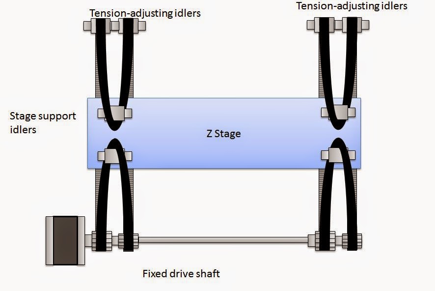
It’s patented but a simple way to make a harmonic linear drive to power Cnc / 3D printers with very high drive ratios and zero backlash! Just belts, different sized pulleys and gears
http://www.animatics.com/smartnews/59-no-gearhead-no-brake-animatics-new-harmonic-linear-drive.html
Has anyone used this setup in a 3D printer or Cnc application? I will build one to test. It seems that it offers improved accuracy, specifically no backlash. The drive rations mentioned are pretty low nothing like harmonic drives for robot arms, but the hardware needed is at our fingertips for cheap. I will probably try first with steppers. But if it’s really no backlash, it could work with servos (closed loop brushless motors).
Ive dreamed of open source hardest/firmware for years, haven’t we all?! But lacking this, I bought teknics servo killers :
They offer closed loop in a self contained package and are quite nice. I’ve tried them with belts, but I was using dual y belts and their support said this was impossible to tune… Back to drawing board. Then we tried them with acne screws but the torque seemed to be lacking since my y axis was incredibly heavy. This linear harmonic drive setup would offer increased torque with zero backlash and looks like a good solution to couple with the tekinic servos… Maybe there would be increased accuracy and faster movement with steppers alone.
Since I don’t know if any open source electronics/firmware that run servos (I assume the host software / slicer would be unchanged), maybe this configuration offers advantages.
The use of belts on Cnc, with very heavy carriages/hardware could benefit from both the torque and accuracy. But there would be a limit to speed with steppers, I would think. I found video examples of the harmonic linear drive in use with a large Cnc using servos, though. I assume it saves money to use belts over acne rods and acme rods are practically limited in length to 3 meters from what I can tell… Shipping sizes, I presume.
So is anyone up to design and build a machine with this setup to test accuracy and other benefits?
The example diagrams show a rather low drive ratio. I know there is always a trade off in design… So I assume the higher drive ratio you use, the less speed you could have access to. But you would get increased torque. I suppose that finding a sane amount of torque / drive ratio for a 3D printer or Cnc would be the goal that translates into increased speed… To meet the limits of hardware and rigidity that you have on that machine.
I think Cncs will run up against the limits of cutting speed for a given router, spindle or cutting bit, but cheap, 3D printable robot arms always run up against torque issues first… Ok, and arguably rigidity comes into play.
Robot arms are an interesting study for these linear harmonic drives… Kuka arms do use harmonic drives. They need high speed (low torque) motors but require low speed movement with very high torque at the joints… Thus, the combination of fast motors or servos (closed loop using encoders at the motor?) and high ration harmonic drives for converting that speed into manageable torque with the magic of (near) zero backlash.
I assume that you can license the patents for harmonic drives, but the hardware is very tough to build and therefore expensive. I also assume you can license the patents for linear harmonic drives, but the simple, lower cost hardware seems to give it an advantage if you are looking for cheap, high speed motors to deliver the high torque at the joints due to the potentially huge drive ratios in a cheSp mechanism you can build at home.
So why has no one, to my knowledge, build a home brew version of this? Or licensed the tech for a Cnc or 3D printer? Since we use belts and it’s all about linear motion, it seems a good fit.
I found a 2009 RepRap post asking the same thing but it didn’t go far.
I also found the patent. http://www.google.com/patents/US8516913
Of particular interest is also fig. 12, 18, 22 which show other embodiments - although I didn’t understand if it was prior art/inventions or derivatives of the new design. All are interesting. They specifically call out the use of this applying to robotic arms.
Note: I saw a YouTube video of a Kuka robotic arm tear down and was surprised at the extensive use of belts. I didn’t investigate further, but I assume they are used to get the weight of the motors off the arm… Not to use this type of system. Anyone who can confirm this?
Thoughts?
Brook


