Hello, I have some difficulty operating the PL9823 (= WS2812B chipset) with FastLED (or others library).
Whether with Arduino Nano or Arduino Uno, pl9823 is difficult to interpret the commands. There are lot of “flash”. Is there a particular arrangement to be made for it to work properly?
For several months I have no solution… :’(
I do not believe the PL9823 uses a WS2812 chipset as the datasheets state 1.71 microseconds bit length that gives a data rate closer to 600Kbps compared with the 800Kbps of the WS2812 !
@CeeeJ FastLED has support for PL9823 - show us your code, and then maybe we can help.
I tried a whole bunch of codes each time with the same result.
PL9823 : http://www.ebay.fr/itm/281872999852?euid=c419d63161b14a68bd6982ec0ba5d886&cp=1
#programming code snippet
#include <FastLED.h>
#define DATA_PIN 3
#define NUM_LEDS 8
#define BRIGHTNESS 64
#define LED_TYPE PL9823
#define COLOR_ORDER RGB
CRGB leds[NUM_LEDS];
CRGBPalette16 currentPalette;
TBlendType currentBlending;
extern CRGBPalette16 myRedWhiteBluePalette;
extern const TProgmemPalette16 myRedWhiteBluePalette_p PROGMEM;
void setup() {
delay( 3000 ); // power-up safety delay
FastLED.addLeds<LED_TYPE, DATA_PIN, COLOR_ORDER>(leds, NUM_LEDS).setCorrection( TypicalLEDStrip );
FastLED.setBrightness( BRIGHTNESS );
currentPalette = RainbowColors_p;
currentBlending = LINEARBLEND;
}
…
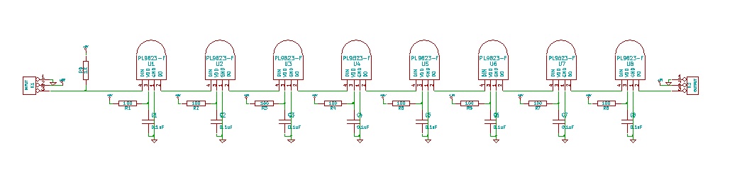
I do not understand the resistors from 5V to the LED ?
What value are they ?
@CeeeJ does a simple “moving dot” sketch work? or does that also flash and flicker?
I see nothing in the datasheet that would require you to add any resistor between the 5V and the LED !?
I would remove them !
The video does look like a timing issue - perhaps we need help from Daniel Garcia…
@JP_Roy I just tried the solutions found on the Internet. Example : http://image02.seesaawiki.jp/r/e/rbbtake/aac4be2399e89363.jpg
This brings no great improvement.
@Stuart_Taylor yes it does but with typical high current switching demands through a resistor, who knows the effect of an instantaneous voltage drop on the IC’s behavior !?
@CeeeJ The link shows a guide for Neopixels not for pL9823.
And nowhere in that guide I see a recommendation to add a resistor between the 5V rail and the 5V pin of a Neopixel !?!?
@JP_Roy “Adding a 300 to 500 Ohm resistor between your microcontroller’s data pin and the data input on the first NeoPixel can help prevent voltage spikes that might otherwise damage your first pixel. Please add one between your micro and NeoPixels!”
I just tested this, but with or without, the result is similar.
…
Sorry I misread !
I have seen here: http://akizukidenshi.com/download/ds/rita/pl9823.pdf
Yes, the resistor between the MCU and the first data pin is understandable but not all the other resistors !!!
Sorry I misread !
I have seen here: http://akizukidenshi.com/download/ds/rita/pl9823.pdf
I see the resistor symbols in the datasheet application note but can not see a recommended value !? Where is it ??
I still suggest that you remove those resistors to 5V !!
Either way the result is similar without resistors.
I think it may be from a timing problem…
Ok thanks for trying that, I still think those 100 Ohms resistors are not required !
I guess you and Stuart are right about this being a timing problem.