HELP!! I have added an extra powersupply to my Prusa Mendel 3d printer. I had to add some length to the stepper wires and replaced some wiring, but nothing in my setup changed. I have measured the steppers and wiring and that all good.
But since i did this update my x, y and extruder motor will not turn anymore.
When i try to manually move the nozzle (x, y) the extruder motor jitters softly, but the x and y motor do nothing.
I am really desperate now. I have no idea what is wrong. I added a resistor to the 5v line but that doesn’t make a difference.
Do both PSU share the ground wire? Did you measure the voltage coming from both PSU between yellow and black wires? Did you try to revert back to one PSU configuration?
you say it worked.
Then the only thing that changed is some extensions on the wires.
You verified power,
If we take you at your word, The only thing that changed is the extensions and the fact it doesnt work any more. Either find what makes that statement false, or the extension is your problem
you might swap psu from one side see if other things stop working. Perhaps you missed something activating the psu . If so it should present if you swap them.
One more thing, I assume your board (Megatronics or something?) has removable stepper drivers, try to swap working stepper driver with malfunctioning one. See if anything changes then. Make sure you didn’t swap any wires from steppers to drivers.
It might be that the longer wires are now acting up (more) as antenna en too much electromagnatic interference is introduced in your wires. Try twisting the wires (or use twisted pair UTP cable). Also shielding can help.
It’s very likely that the power supply for the steppers is not going into full switching mode. There is a minimum power requirement to get a clean regulated output. The steppers draw very little current at idle. There is not enough load on the 12v line. You can easily replace the 12v supply to the board with a 90 watt power brick if its not powering the bed.
How did you hook up the second supply to the bed? Are you using a relay or otherwise isolating the power supply?
@Marky_Cee i will try that. I bundled them together with tiewraps.
@Stephanie_A the second powersupply it’s ground wire is connected to the ground of the first supply and the 12V wire is going directly to the bed. (The mosfet for switching is attached to the negative side of the bed)
So to be clear: psu+ to bed+, bed- to sanguinololu bed- connector.
I tried twisting the wires and hold them apart, but no difference. I should say that the z motors are working fine (those are extended too) and the x axis (wich is not extended) is not working. So to me it looks like it is not a wire problem.
Also the motors can be moved freely. Or in other words, they are not powered or held in place like they normaly should.
For the printer itself, i still use the original powersupply that has been working fine since i got it. I only added the second one because i couldn’t get the bed higher than 67 degrees celsius.
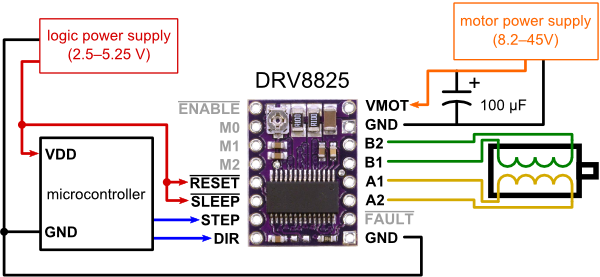
Stepper motor driver has two control pins, STEP and DIR (look here: https://a.pololu-files.com/picture/0J4124.600.png?91f6a95b143bbb0f34f82c30a47fcced). Detach stepper motor driver board and plug a LED + 1kOhm resistor between STEP and ground. When you drive the stepper from printer control software the LED shall blink. If it’s not then either you inverted LED polarity or your control board has problem. Bad contact or microcontroller output pin burned.
