First, thank you for this resource. I’ve referred back to it frequently during my conversion to Smoothie (on MKS SBASE, not ideal I know) on my K40. I’m in the home stretch but have run into an issue with PWM. The laser works and it cuts wonderfully, but PWM seems to always fire at full power. I used @donkjr ‘L’ method with pot for overall intensity control.
I’ve read elsewhere the pot may be to blame. The pot definitely controls intensity in that I turn it and I see the mA moving up and down, but when engraving a grayscale image the meter reads the max 17mA constantly.
Have tried various changes in smoothie settings (200 and 400us for pwm timing, different speeds, etc), but there are no changes and PWM stays at full intensity as set by the pot.
So here’s my questions:
Linked is the pot I’m using. It’s pretty high quality, but maybe it’s the wrong type for this application? As mentioned before it definitely controls the overall intensity consistently and linearly.
What test methods can I use to rule out the pot, temporarily bypass it as 5v and set smoothie max to .7?
What else do I need to try to get PWM to actually control the intensity? Would trying a different pin on the board make a difference? I’m using the standard 2.4 and it is definitely controlling the laser on/off properly.
Never seen a pot like that :). I don’t think it is a pot at all rather a hall effect position sensor. It may work depending on how it is hooked up IE: the output provides 0-5 V to the IN pin.
Are you getting an image while engraving?? If yes post photo
If you are not getting an image reduce the pot to 0 and then increase until you get an image.
@donkjr Yeah it is a positional sensor from an old project. It serves the exact same function in that it has 3 poles and returns a variable voltage based on position though. I was concerned that maybe the hall effect wasn’t responsive enough for the PWM, if that even matters, maybe?
@Nathan_Mueller Very useful video, thanks
The pot setting is independent of the PWM so I doubt that it is the culprit.
Checking … Looks like you have the output of the position sensor connected to IN and your PWM (without a level shifter) is on the L pin of LPS … right?
Some observations from the video:
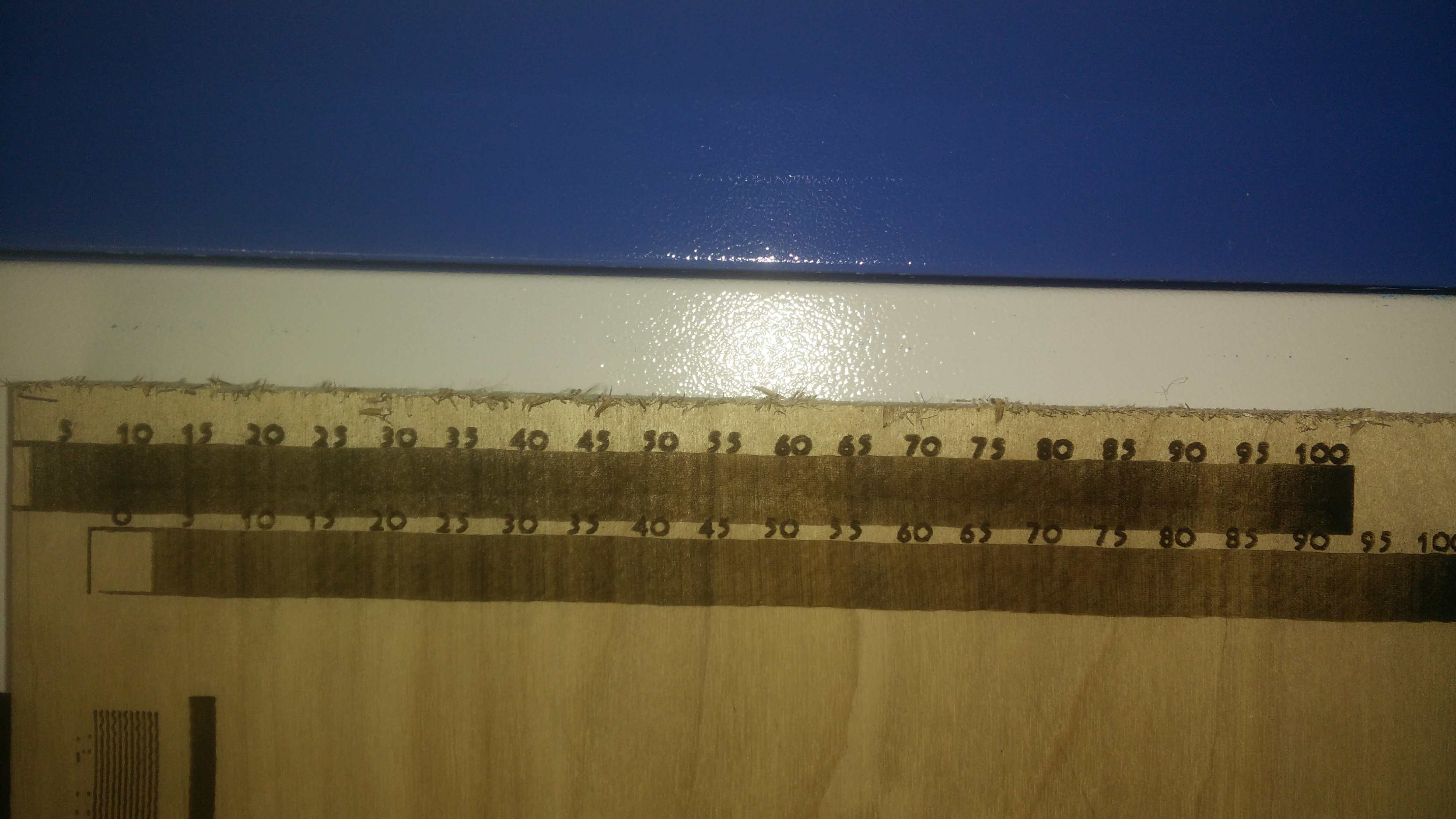
The characters are printing so the PWM must be working correctly I.E. turning on and off at the correct times. However you are not seeing much of a change in grey scale.
There is faint changes and a darker area at the end of the pattern suggesting some host control of power. Then again this can be an effect from the carriage slowing down or reversing.
Some ideas regarding the source of the problem:
3. The PWM is working but you cannot resolve it in the image because the laser power supply setting is saturating the power control.
4. The speed is to fast for the power control system to resolve the changes in power.
Stuff to try:
5. Slow the engraving down significantly and find the point at which you can resolve grey shades while at the minimum power setting on the pot, (if that point exists).
6. If nothing else points to the problem, you can test and verify that the PWM is working properly by statically sending it Gcodes with various power levels while hanging a DVM on the PWM signal. Approx values; 100% = 5V 10%=.5 etc.
I would try #5 first… and then we can go from there.
@donkjr OK, so it seems that the pin I’m using for my PWM is providing a default volt of 24, and while running it is providing a % of that 24v. Basically its >5v at pretty much every point except when it comes across white pixels and drops to 0v. So that is the problem discovered.
The question is why is that pin outputting 24v? Is that normal? I remember seeing people using step down boards, so perhaps this is why. I didn’t think they were required but I may be mistaken here.
@Nathan_Mueller interesting. Do you have a schematic of that board. It could be that your open drain connection is set up or wired wrong. These outputs can usually be configured for to be pulled up to 5V or 24 V or just open i.e not connected to a supply. You want yours open drain that means that the drain of the drive FET is not pulled up.
I do not have a schematic, only diagrams with pinouts, such as the linked image. I have ‘L’ hooked up to the negative pole of 2.4, ground hooked to 2.5, and ground/24v to power.
One thing to note is that these boards do not have any method of supplying 5v that I can see. It is being powered by 24v, and has a USB connection which may or may not be giving it 5v.
I’m not too educated on concepts like open drain, etc. How would I properly config this? The 2.4 pin I’m connected to is on a MOSFET, and there are other PWM capable pins that are not, such as P1.23 in the upper left.
Here are the relevant connections:
24v+ to board power
Ground to - on board power
Pin 2.4 neg to L
Pin 2.5 neg to Ground (not sure this last one is appropriate)
@Nathan_Mueller an open drain configuration is a MOSFET whose drain is connected directly to the load. It is like putting a switch from “L” to ground. “L” turns on the laser when it is connected to ground.
The (-) of P2.4 (normally the fan?) should be connected internally on the the board to the drain of the MOSFET and nothing else. You can check that with an ohm meter or by tracing it. If you connect an ohm meter between -P2.4 and the 24v supply it should read open.
…
At a glance it looks like you have “L” connected correctly. I assume there is a single wire from -P2.4 to the “L” pin on the supply.
…
Pulling 2.5 to ground is not correct and would be shorting the MOSFET’s drain on that pin to ground. It probably did not create any damage but is not needed as you are not using that pin
…
That does not explain how PWM is being driven from 0-24V unless somehow the -P2.4 pin is connected to the boards 24V.
Not having a schematic I am guessing but sometimes there is provision for the drain (-P2.4 in this case) of a driver to be pulled up through a resistor to 24V. You would find this as jumpers etc on the board.
…
@Jorge_Robles if I recall correctly you are using one of these boards do you see anything wrong withe @Nathan_Mueller connection? How did you connect “L” to the MKS SBASE and how did you set the smoothie configuration?
I’m using GRBL-LPC with L at -P2.5. I did test using a level shifter with 1.23 on smoothieware and was working ok either. Have to retire the MKS in favor of @raykholo C3D board soon. I only use L, not IN
@Jorge_Robles@donkjr Thank you. I will try -P2.5 tonight and report back. A question for my own understanding: when defining a PWM in smoothie, is the firmware hard-coded to know that it should be a 5v signal? Where does the 5v come from if the board is being supplied 24v?
@Nathan_Mueller
You should not have 24v anywhere on the P2.4 or P2.5 ports, if you do something is wrong.
The “L” pin on the lps only needs a ground, no voltage.
The lps has an internal 5v supply.
After more testing and some research, I’ve discovered that the indicator LEDs attached to the MOSFETS were causing the 24v reading when using the multimeter. I yanked off the LED on 2.5- and tested with a DMM. I now get readings in the range of 50mV-4v when running some sample gcode with the laser disabled.
What hasn’t improved is my engrave quality. I have the same problem in that there is no distinction in shading, and the ammeter seems to be confirming that there isn’t any variable power happening. So the readings are different, but the laser is behaving exactly the same as before. It works in that it turns on and off at the appropriate time, but has no variable power I can determine.
Next steps I’ll try are:
-Setting IN to 5v and controlling overall power in software to rule out any possible variables.
-Could algae/contaminants in my water be causing issues with fine control? I can try adding some disinfectant.
-Try using the PWM IN method to see if I get better results. I’ve been having trouble finding appropriate instructions and don’t have a full grasp on how to wire it up, as it seems more complicated than the L method. IN doesn’t actually fire anything, so would there be a separate signal going to L to control laser fire? Is that achieved using custom M codes and the switch module?
-Flip a table and buy a 3d cohesion board… I’d rather not as that is significant cost and I’m already over budget with the foreman (wife). This also runs the risk of not solving my problem if the issue isn’t with my board.
-Use an Arduino+Shield with GRBL. I didn’t realize that was an option until just now…
@Nathan_Mueller
“I now get readings in the range of 50mV-4v when running some sample gcode with the laser disabled.”
Did you try to send individual G codes one at a time with different power values while reading the “L” pin? This will verify that the PWM if fully working.
“-Setting IN to 5v and controlling overall power in software to rule out any possible variables”
2. You can do this same thing by just turning the pot full on. However I think this will make your problem worse since that will max the power all the time and the software settings will be less visible.
“-Could algae/contaminants in my water be causing issues with fine control? I can try adding some disinfectant.”
3. I doubt it however to have a healthy HV system you need distilled water with algaecide. There is a complete post on this on my blog. Do not add any other chemical.
“-Try using the PWM IN method to see if I get better results.”
4. You can but it brings with it lots of complexities and side effects. The L control schema works you just have to get all the factors in sync; speed, pot setting, PWM signal etc. Now that you have the correct PWM signal I would again try lowering the pot until you have no marking and then bring it up slowly to see it that makes the grey shades apparent. Do this at very slow speeds.
“-Flip a table and buy a 3d cohesion board… or use a Arduino+Sheild.”
5. I doubt that this is simply your controller although changing things up sometimes finds the real problem :).
I still think the problem has to do with the PWM signal not having enough effect on the overall power as the POT control is overriding the PWM control (a weakness of this LPS control schema).
Others have had this problem I encourage a search of the community and I will do the same to look for more ideas.
For now I recommend testing discrete Gcodes with power settings from 0-100% in 10% increments while measuring the PWM voltage.
Also turn down the pot until the image disappears and then slowly turn it up. Try lower speeds.
Post the results and hopefully that will point us the right direction.
Slowed down the speed and set the power to the lowest setting possible. Also set the to diameter to 0.1. The engraving is still quite uniform, and in fact it looks like the darker pixels were engraved lighter, not darker. You can’t see any of the vertical lines between the increments either.
@Nathan_Mueller i am not sure that he used IN in the end configuration but I can assure you that single wire “L” PWM works when everything is setup. As I said before driving IN with a PWM signal has its own problems.
Here is my suggestion for a starting point:
Experiment with settings start here:
…pot =9ma,
…speed = 200mm/s
…laser diameter= 0.2
…laser_module_pwm_period - 400
…insure you have fresh distilled water
…
Run the PWM voltage test from Gcodes.
I agree. If nothing else hopefully this thread has some useful info about pulling the LED on the sbase controller- as that is still required- and is a reminder to check your code carefully, as the file was downloaded with the settings commented out.
Here’s my first finished piece! Not exactly the best example of shading with pwm, but I’m still super happy with it.


