Happy me!!! Amazing what one learns once they try reading things with a clear rested head!
Ran back over a bunch of the diagrams, and info from other posts and the wire from 7 was supposed to be to the K+ instead of the K-!
Swapped it over, powered up and hit the test button on the panel… finally that beautiful glow I havent seen since before christmas!
Again… Thank you @donkjr and everyone else that either helps or posts their problems here so that we all get to learn a little something!
@Frank_Dart so funny. I just completed the below drawing. It suggests that the K was wired wrong.
I also updated my blog to make it more clear.
Curious; Is you “Laser Switch” on 'D" working ok. I had another user could not get that to work.
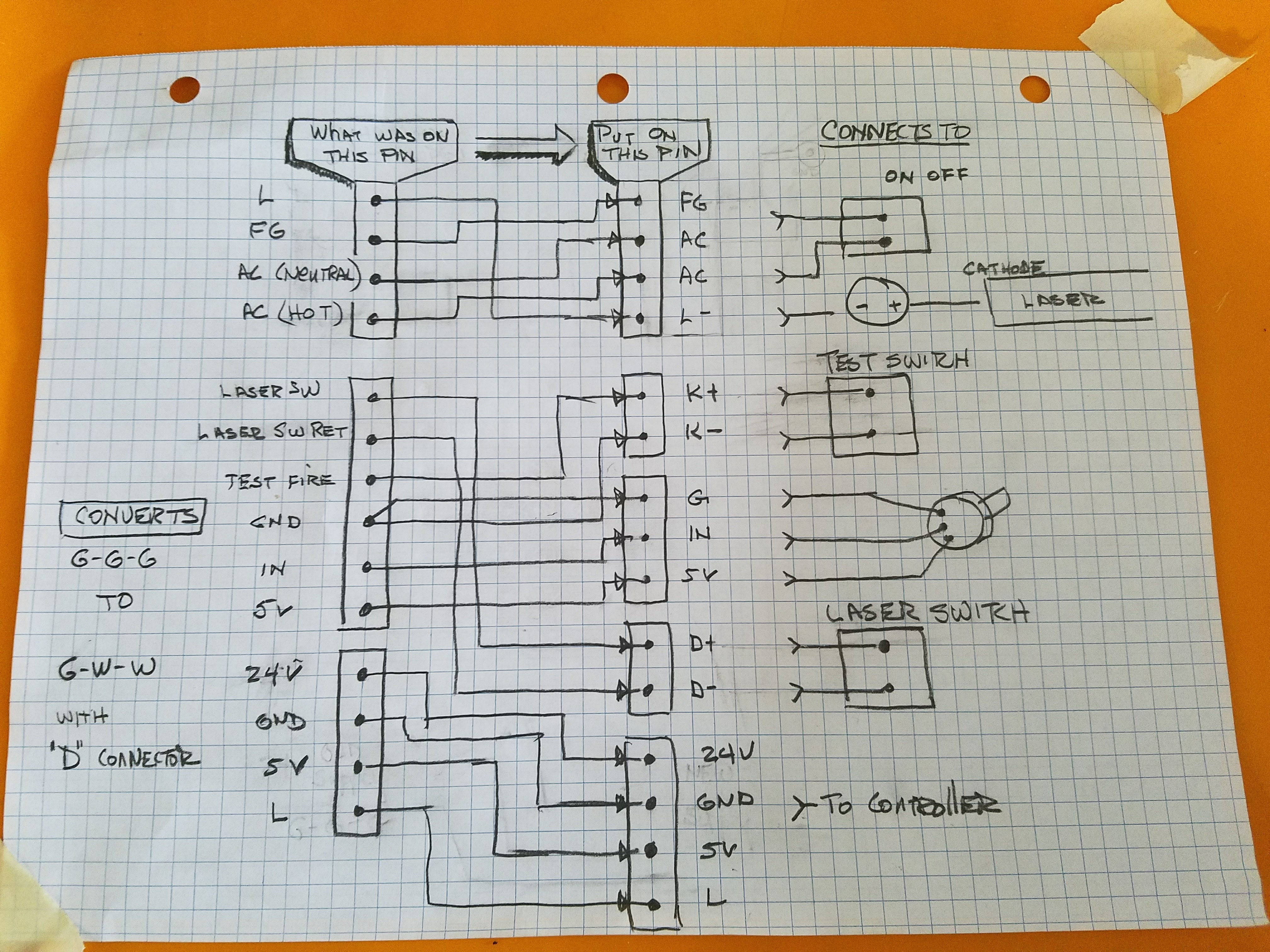
For anyone looking for the finally markup:
In the end, this is how mine was wired.
Be very cautious with 1-4, most documentation
around shows that these match up directly, but
mine did not, check the labels on the board!
Shown as top pin → bottom pin
1-4
2-1
3-3
4-2
5-10
6-11
7-5
8-7
9-8
10-9
11-12
12-13
13-14
14-15
XX-6* nothing connected to bottom pin 6
Sorry @donkjr I didnt see you had posted about the same time I had.
I have only done just a quick fire test so far just to see if things worked as I dont really have it wired up properly with real connectors yet or the cooling,etc.
Now that I know the lps and the tube work, Im going to get everything wired properly instead of just twisted on and covered with electrical tape.
So are you asking if the laser will still fire without the loopback on D?
I didnt have any actual safety switches on the original and can see it just a short loopback in my top picture labeled 5 and 6.
@Frank_Dart Yes if you disconnect the D+/_ will it still fire with the Test button?
@donkjr Ok that is not good. That should be the interlock/safety circuit. That is exactly how the other “D” supply I worked with behaved.
That means that your “Laser Switch” is not doing anything and you cannot install interlocks, water flow sensor etc.
Can I ask where you got that supply from and do you have part #, any interface documentation etc?
I havent tried it without the loopback, and I got it 2nd hand from someone in the fb group that was parting out an old k40 the same time mine died, so no documentation, but I’ll certainly take a closer look and see if I can find a part #
@Frank_Dart OMG I read my question to you as an answer from you… doing to many things at once 
Take a break man, or at least cut or engrave something on your own machine and for the love of god turn off the internets so you dont feel compelled to save us!
Ok… if you’re still reading this, it means you didnt take my advice.
You my friend, must be able to see the future…
I did just try it and it fired without the loopback, it also fired using the test button with the power switch off… scary stuff man.
R1407779 is the only thing that resembles a part # on the board.
A blog link that may have something meaningful… or at least is the same supply he used in his build
and another pic of mine… dont mind the shoddy wire job, as I said that was just rigged to see if it worked and will be wired properly.

@Frank_Dart heh, cant see the future, just been there and done that . I noticed on the blog link that you sent me it did not look like that machine had a “Laser Switch”.
We must not understand what the “D” really does.
I don’t know why the “test” would work with the main power switch off unless the LPS is not connected on the correct side of the power switch?
- Where are the 2 AC wires connected to?
We never figured out what was wrong with “D” on the other one but I am willing to keep working with you till we do :).
Do you have a multi-meter and are you comfortable with it?
2… read volts on D+ to ground when the LPS is on
3. read volts D- to ground when the LPS is on
We might have to take a close up picture of the back and front of the board so I can see if I can trace the “D” circuit.