After many hours I managed to have FastLED working on Atmel 7 without having to use the entire Arduino bootloader. Right now I’m able (with very little modification) to compile and execute all those beautiful demos from examples directory. I’ve already read almost everything on Wiki page and find it very infomative. My goal is to reproduce a variation of the lightning effect on starship engines from the video, and I confess I’m a little lost here. Someone could please give me some hints/directions? It appears to flick and fade while the brightness increase. Colors seens to change a little bit too. Please, my scale models needs your help! Thanks! http://www.youtube.com/watch?v=92YmkG-RSBE
Ah! I have some ideas here. I’ll share them and maybe they’ll be a starting point for some code.
First, id divide into three problems:
The ramp up in brightness from off to full on.
The color palette. I’d make a color palette that was LIKE the FastLED built-in “heat colors” palette (black to red to yellow to white), but matches the video better: black to red to yellow/orange to pale purple?
The flickering.
So:
I’d first write code that just ramped up the brightness from full off to full on-- never mind the color or flicker. Just use red for the hue and ramp up the brightness:
c = CHSV( HUE_RED, 255, brightness);
Get that working: slowly ramp up the brightness.
Then switch from HSV to using a palette, indexed by “engine temperature” (0-240, let’s say)
c = ColorFromPalette( myPalette, temperature, brightness);
Get that working: slowly ramp up temperature AND the brightness.
THEN I’d layer on a flicker effect, sort of like this:
if
brightness > half &&
temperature > half
Then
randomly about 1/10th of the time
Dim one pixel by 75%
Endif
(Note: that ain’t “C” code. At all)
But basically: divide the effect in to its specific components, and get each aspect working one at a one separately before adding in the next layer of complexity.
Mark, your explanation gave me a clear path to follow. When I arrive in home afterwork I will try to produce some code based on all that valueble information and the pseudo code you gave me. Thank you very much for your kindness!
I’m using timer1 to generate millis();
I’ve tried to use #define USE_GET_MILLISECOND_TIMER 1 and of course declaring a function to return millis() as expected but still the same.
One thing I’d want to rule out is brownout or similar power issue. Are the LEDs and the microcontroller on the same power supply? And if so, how many LEDs are there, and what’s the power source?
The reason I ask is that it might be that at full brightness and a very ‘white’ color, the LEDs will draw a lot more current than when dim and more saturated.
It’s just something I want to rule out before digging in deeper on the software side.
Lower bright isn’t freezing. Seens like a bad DC power supply. I have only 5 leds, as you pointed out. I will replace and report back! Thank you again.
Wow, that’s amazing! Are those just little backlit transparencies or similar in the cockpit? I saw the mention of “etched set” in the YT vid, and am assuming those are inserts of some sort.
Hi @John_Hendy
I’m not the builder of that model you saw on the very first post video, but I have to agree, It’s an amazing work from the very talented scale model builder Will Vale!
When building those models, the use of components in the intent of add extra details not present on the plastic is a very common practice. Those kits are made from mold inject polystyrene and some details are difficult to obtain due to manufacture process limitations.
To fill this lack some small companies offers extra parts found called ‘aftermarkets’. They can be found in several forms, like waterslide decals, resin cast or metal machined parts, etc.
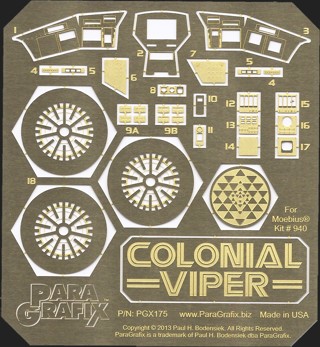
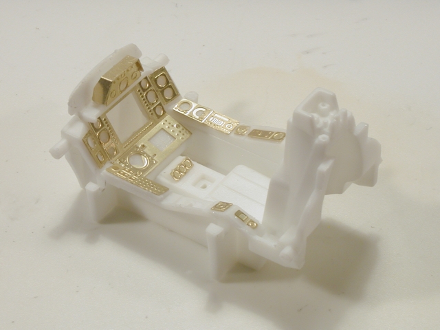
By etched set, the modeler was refering to a Photo Etched set. Those are very detailed pieces produced using very thin brass or stainless steel sheets (0.1-0.5mm) corroded by chemical or electrical process. Something very simillar to the PCB manufacture process.
I believe the modeler had used decals and printed acetate + photo etch set from Paragrafx + fiber optics to achieve selective illumination on those very small panels and buttons.
My english isn’t good, so I’ll let the images speak: