How is the Nano being powered? Via the USB?
Here’s my thoughts:
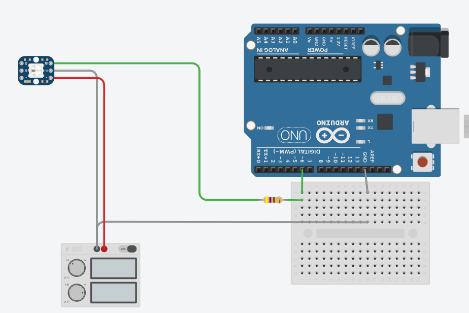
- Try disconnecting (temporarily) the 5V supply from the LED’s and connect them directly to 5V pin on the Nano.
- Power the Nano from the USB on your computer (via mini USB).
- Remove the resistor to the data line.
- Program the Nano with a simple example and see what happens. I use pin 12, but whatever.
If that all works, you could:
- Disconnect the USB.
- Connect the 5V supply to the LED’s and to the 5V pin on the Nano.
- Reconnect the resistor (I never do).
FWIW, the top section is how I power/develop routines with my own Nano’s and a strip of 60 APA102’s. The bottom section is how I run them in production and I have a LOT of Nano’s.
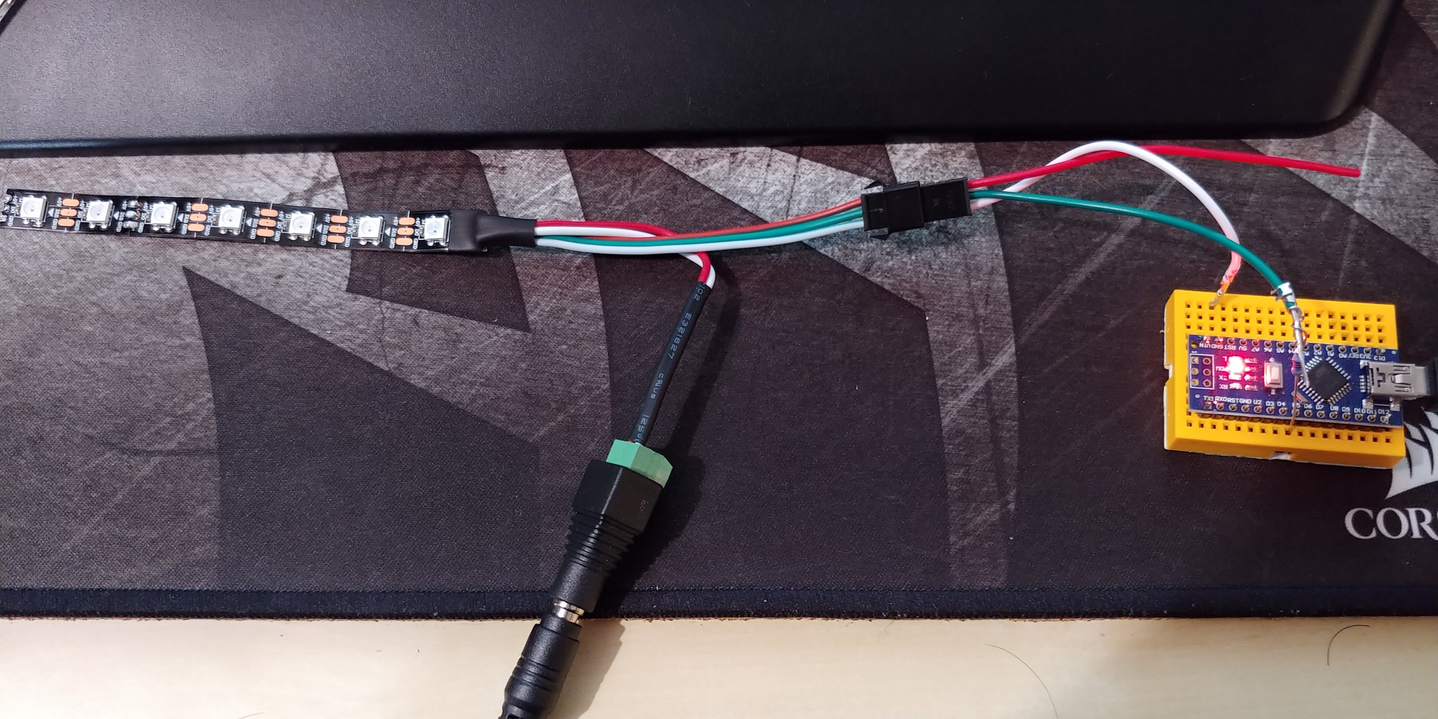
The only idea I have is that it doesn’t look like your Arduino Nano header pins are actually soldered to the Arduino. I could be wrong because I’m just going off what I can see in this picture but that’s what it looks like to me.
It also doesn’t look like your data pin is going in to pin 6 like your drawing has.
If the connections are all correct and soldered, try without the resistor in the data line, or with a much smaller resistor
@Daniel_Garus could you check the voltage at several point of the strip ? Maybe The first led is dead. Ps I had the same issue with couple of led strips ordered from amazon too. I had tested the circuit with one strip and the same with other strips would not work whatever I did.
@Daniel_Haber Indeed it doesn’t look like the data pin is going to pin 6. You’re also right in that it doesn’t looks like the headers are actually soldered to the Arduino. Then there’s the 5V. Yikes!
Thank you all for the input, I will try it this evening.
About the data Pins, I played around with them a little bit and adjusted the code so the Pin should be correct.
@Andrew_Tuline what about the 5V? (Genuine question^^)
@Daniel_Garus The red 5V wire was not attached to the Arduino. That would tell me that you are probably running the Arduino from the USB. How about the grounds? Are they tied together? They sure should be.
It just seems to me that you need to sort out your power and to make sure your connections are solid. They sure didn’t look it on that photo.
I feel like an idiot, soldering the pins correctly did the trick.
In my ignorance I assumed, that using the breadboard would suffice.
@Daniel_Garus learning is part of the process and the beauty of it
Thanks to all your input I was able to finish my ambilight 
Here is how it looks: