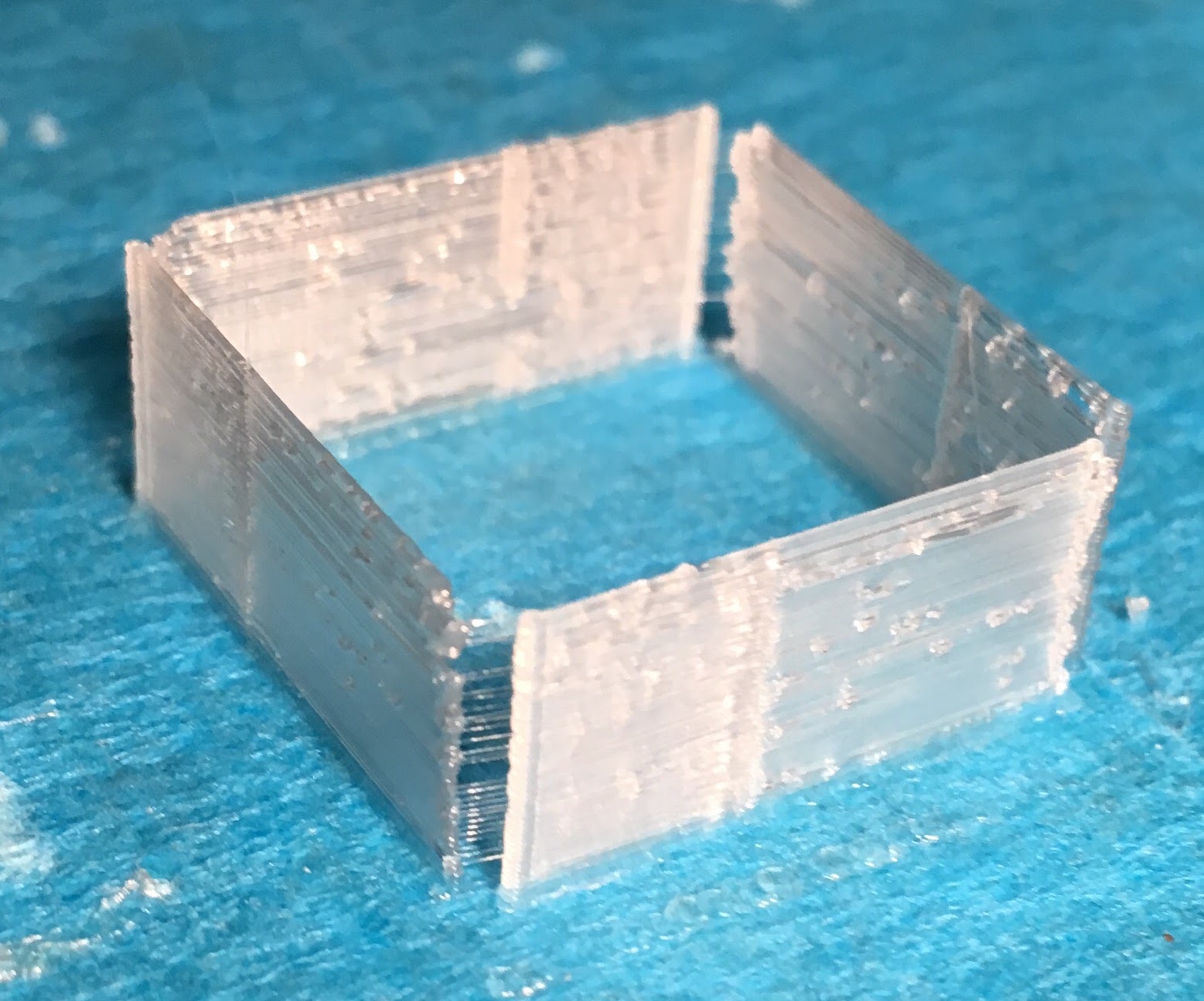
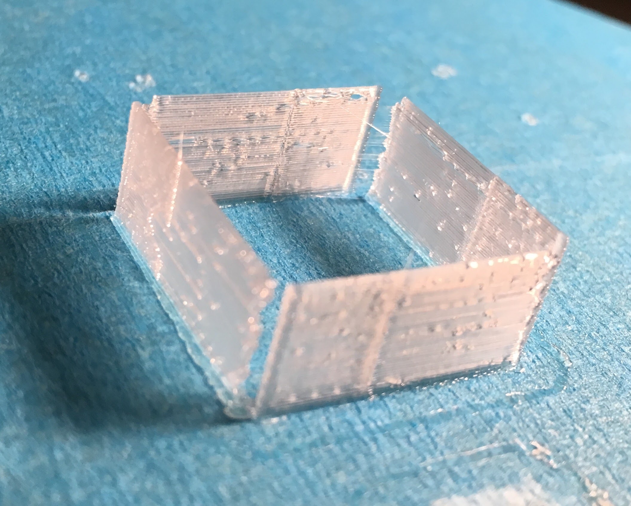
I always thought that manufacturer’s claim about 100µm (or, by some, 50µm) resolution from ø0.4mm nozzle applied only for layer height. But when I measure these vertical thin walls (from the Makerbot calibration set), they are 0.1mm in horizontal thickness. That means a ø0.4mm plastic jet condenses into some 0.1mm structure. How does this work?
Other than this, I see some uneveness on end edges as well as in the path. I guess this is the doing of material? How do I evaluate the printer in regard to thin walls?
You get a wall that’s smaller than your nozzle by extruding slowly and moving quickly, at least relative to normal operation. That way the extruded tube of plastic gets pulled along and stretched to be thinner than its original extrusion width.
As you’re seeing here, though, that technique has its drawbacks and is the reason your perimeter width is best left slightly larger than your nozzle size.
If you do want the ability to make finer surface structures or thinner walls you’d want to switch to a smaller nozzle, there are a few out there and some people have had success with using an airbrush nozzle with an adapter to the now fairly standard E3D nozzle threading. They’re not particularly common, though, because small nozzles increase the difficulty of printing and decrease the fudge factor available to you.
The smaller the nozzle the greater the back pressure on the flowing filament, and the smaller the window in which things will properly extrude without grinding. I’ve seen people have great success with them, but generally speaking a smaller nozzle will take more playing to get good settings and will be more unforgiving of filament variations.
If you want really fine surface details you may have to resort to a photo resin printer.
Appreciate the info, @Stephen_Baird . I am just evaluating the quality of Ares 3D. (Simply replacing filament gave me a great deal of hesitation. My head might explode to think of replacing nozzle.)
What they mean is 100microns layerheight and the accuracy of the steppermotors not the linewidth…
@VolksTrieb Hence my marvel when I see 0.1mm wall built.
@whackyhack what settings did you adjust for this? Extrusionwidth? Well possible it is. The extruded plastics may be pulled along but when you do that you have no pressure in the nozzle and that may cause blobs and later line beginning. You need to slowdown a lot. Also you wont have control of where the line is layed down cause it can drift according to nozzlesize. I use 0.35 extrusionwidth on top solid infills to make better suface and it works but mostly i use bigger line width because it looks better.
@VolksTrieb I didn’t make adjustment to print this. I didn’t even read Thingiverse descriptions in detail, only noticed the file name 0.5mm_single_wall_calibration_piece.stl… Mmm. Looks like even “0.5mm” didn’t register, as evidently the wall measured 0.1mm instead.
Guess I’ll have to open it in meshmixer or something to measure the design.
The model is http://www.thingiverse.com/thing:2064/. 0.5mm comes out as 0.1, this is odd.
Huh, that model should come out as a single perimeter wall that’s the width of whatever your slicer has its wall width set to. Are you sure something isn’t funny in your slicer settings?
@Stephen_Baird Do you mean the STL doesn’t specify a thickness in this case? Then it’s possible that my slicer was left with 0.1mm wall width from an earlier test. Thought I reset it already. This is very educational. Thanks!
No, the STL should have .5mm walls, but with an extrusion width of .4-.5 slic3r should just round that to a single wall width. Newer versions of slic3r may behave differently, it has been a while since I had to do this sort of calibration, and cura or simplify3d or another slicer may act differently, but in my experience you should see a single extrusion width wall using a model like that.
For the wall width to come out so small would strongly imply that something is set wrong in your slicing parameters. I had actually assumed you had changed the wall width setting in your slicer to get it to do that.
@Stephen_Baird correctly thats why I asked him. Either something wrong with the e-steps or slicing settings
I checked my KISSlicer settings which hasn’t changed: Layer thickness 0.2, extrusion width 0.4, inset surface - whatever that is, 0.1. (Tooltip for Inset Surface says “Adjust the surface inward (in X, Y plane). This should be ≤ Extrusion width/2.”)
@whackyhack Inset is just a measurement adjustment. If you dont have problems with the overall dimensions dont use it (zero it). But back to your phenomenon there. Seems slicersettings are ok then. Whats the extrusionfactor and did you set the filamentdiameter correctly? Did you do a e-steps calibration?
Flow rate factor is somewhat equivalent to “Flow Tweak” in KISSlicer, I think. That is 1. Yes, I have adjusted for diameter. No, I didn’t perform e-steps calibration. (Have yet to read up.)
Well mark your filament @ 100mm above the extruder and let it run through 50mm. Wenn you got 50mm left your on the right way. When more or less you need to set your e-steps in firmware or eeprom