i connected my co2 laser to grbl on the spindle enable pin. And when i measure with my scope i can see that its outputting the pwm signal to power the laser (1ms laser test is not 1 ms). but it wont fire the laser. i think i need to connect the laser high or low ttl. anyone knows how i can wire my laser psu to grbl? i have these connection on the laser power supply.
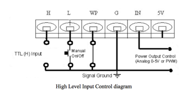
i have connected the pwm out from grbl to the “IN” pin and the ground to “G” but i guess that i need to connect the ttl(H) to grbl as well but i cannot find out to what pin.
Best to move this to the Laser Cutter and Engraving Forum.
The IN pin is an analog input and depending on the output stage may not be compatible with a processors output ( I do not know what hardware you are using). If I know more about the hardware I can further advise.
You may have an “L” signal on the rightmost connector. L needs a ground so connect it to an open drain or collector from a PWM capable output. Insure your config file matches your I/O.
If your supply does not have a rightmost DC power connector then you may have to connect your PWM to “L”.
Post picture of controller and LPS connection points please.
Insure that WP is ground (usually the “Laser Switch”.
Stay away from the leftmost connector its all AC :(!
I have connected the pwm to pin “IN”, grond to “G”, water flow switch between “G” and “P”. And currently nothing to “H” and “L”. I can test what it does when i connect pwm to H or L tonight. What should i do with the “IN” pin?
…either connect “IN” to 5V or put a 1 or 5K pot across:
5VDC one side of pot
IN wiper of pot
Gnd other end of pot
Note: you will eventually need a pot anyway.
Your supply does not have an DC connector so use the “L” for PWM. Later we can consider how we setup the water and interlocks.
INSURE THAT THIS SUPPLY IS GROUNDED
Check that FG (in the AC connector) of the supply are grounded to safety ground.
If it is installed in the machine the Red wire connects to the tubes anode and the white wire (on the back of the supply) connects to the cathode. Usually there is a current meter in this ground (white wire) circuit.
I don’t know for sure but I think the white cathode wire is connected to FG inside the supply, you should check.
------------------------------------
To test throw the switch on P to ON and then ground the L pin. (you could put a PB on L to ground.)
Are you running a 100W laser? This is a 100W power supply?
…
WARNING THIS SUPPLY WILL OUTPUT LIFE THREATENING VOLTAGES OF OVER
<b>40,000 VOLTS!</b>
Here is how we wired a similar supply to a standard M2 Nano. Note that the LPS connectors in the drawing are reversed in position on the supply.
…
Is this your supply? If so an interesting MA meter on the top of the cabinet? Also this site has some more technical info.
I like this statement from the specs :)…
“TTL level is to control the on/off of the laser with an anomalistic protective switch to check water-flow and ventilation, etc.”