I’m a new K40 owner and I’ve picked up some interlock switches for added safety. Trouble is, I don’t have much experience with wiring high voltage systems.
My research tells me that these should be wired using the positive side, and that most people wire their interlocks in series so that if any one of them is tripped, the laser can’t fire.
Sounds good so far, but I don’t know a) what gauge wire I should use, and b) exactly how to introduce these into the K40.
My current thinking is to hook these off of one of the two wires leading from the red toggle switch in front to the PSU.
See borrowed photos from a different post. This looks like mine.
The interlock switches I picked up are:
I’m also likely going to pick up at least one of these too:
Am I on the right track? How would you wire the reed switches in series?
Thought I had seen that pic before… I would use a micro switch like this rather than reed switch.
Simply wire them in series with the switch identified in your post. (I would take the wire out of pin 5 and take it to the micro switch and then take the other side of the micro switch back to pin 5) if that makes sense. Can’t help with water flow as not got to do that myself yet.
Do not wire them into the HV Supply ! - simply put them in series with the ‘LASER’ button wires ie: take one wire off the laser button put it on one terminal if the interlock run a wire from the other terminal of the interlock back to the vacated terminal on the Laser switch - that way both the interlock and the laser switch have to been activated to fire the laser. Easy Peasy
Oh, one more power-related question: I bought a DC powered inline ventilation fan. I don’t have a desire to use the stock power outlets, as they’re a non-standard fixture type and I’m not convinced they’re either wired correctly or rated for this purpose.
So two parts:
How would I wire in the fan to the PSU so that it powers along with the main?
Would removing those two outlets help at all? (Are they just taking up space on the PSU that I can use for other stuff?
@greg_greene is the “Laser” button wired into the enable of the LPS? I think that is the left two wires on the middle connector of that supply. If so I agree with you and that is what I meant by the enable circuit. If not I would be concerned how it is being controlled.
That is also where the water flow switch can be installed.
@Bob_Buechler Not sure what outlets you mean connected to what PS.
The only DC (unless your machine is different) is the 24V and the 5V on the LPS. Those are only rated at 1A each and cannot handle the load of a motor. I would not want a motor on the same supply as the controller anyway.
If you have a separate DC fan you would need to add a DC supply and you can wire its AC input to the same AC as the LPS so that it comes on at the same time.
Alternately, for a long time I just had the machine and its accessories all (fan, water pump, external DC supplies etc) plugged into a switched power strip.
“take one wire off the laser button put it on one terminal if the interlock run a wire from the other terminal of the interlock back to the vacated terminal on the Laser switch”
@Bob_Buechler Just going to reiterate do not hook into the HV side!
If the two wires are going to and from the switch that turns your laser in then it shouldn’t matter if which wire you use if it is like what is being recommend (non IC), but this needs to be on the 5v or 24v side of the circuit.
Speaking from the way my machine is connected, yes Don, it is wired to the enable of the LPS, so all the interlock is doing is adding another switch in series. This way both switches must be ‘closed’ in order to fire the laser, if either is open ie: Cover not closed or Laser switch not pressed then the laser will not fire. Since it is in series it doesn’t matter which wire - or side of the switch is used.
@greg_greene great then we are talking about the same thing. It would be great if someone drew a wire-ing diagram for this style machine so that when we are helping folks we wont get confused and provide bad advice.
Here is an interlock post that may help: http://donsthings.blogspot.com/search/label/K40%20Interlocks
@Abe_Fouhy@Bob_Buechler it scares me when the word HV shows up when talking about interlocks.
The voltage in the interlock loop is 5V which comes from the interlock loop on the LPS.
I beleive on this LPS its the leftmost 2 pins on the middle connector (but it can be traced to make sure).
This drawing shows what I hope we are all trying to advise
As per what + Don Kleinschnitz said that’s what I have done. However what I would do @Bob_Buechler Is check the wiring that goes to the sockets as you will probably find that one of the wires connecting it from the EM switch to the plugs (and LPs) is just twisted around the supply cable and then heat shrink put over it. (That is hidden in the loom area that is in the black cable wrap)
I found that the plugs on the back of mine are good enough so haven’t changed it. Only added a third one to power my air pump.
@donkjr am I correct in reading your diagram that you’re using the 5th wire (one in from the left) for this? I know it shouldn’t matter, but I just want to verify.
Also, re the reference to HV, sorry for the scare. As mentioned initially, me = noob. At first glance I wasn’t sure which end was up, let alone that there is a HV and a non-HV side (but of course there would have to be). I’ve since learned a lot more, so thank you to everyone who helped out here.
My switches have three ports instead of two because they can be used as both NC and NO switches based on how you wire them. Would I feed the NC wire into the COM wire on the next switch in the series and then at the end of the series wire the NC wire back to the switch? Or does it matter?
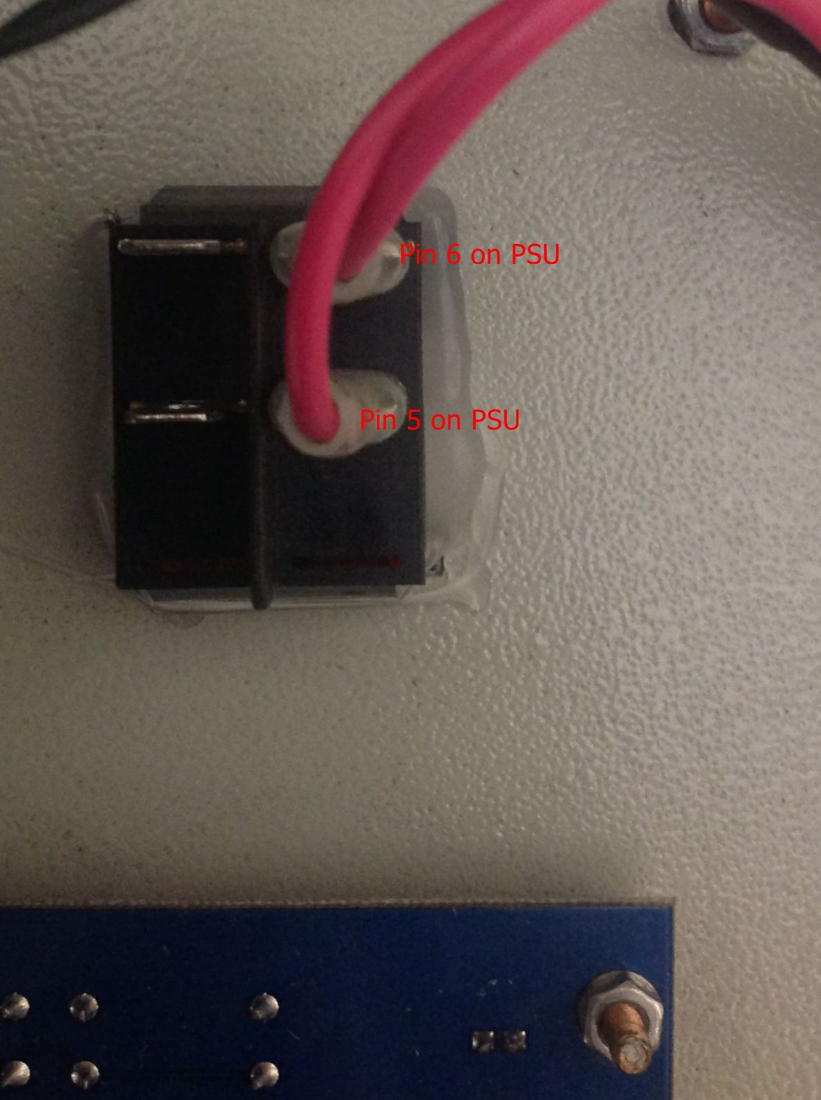
This is how mine is wired. You will need to check that the connections 5 & 6 go to the laser switch first, as what I can gather is there are allot of different layouts, wiring and designs so you need to check first…
You will see by @donkjr blog spot http://donsthings.blogspot.co.uk/search/label/shop to give the general layout but YOU need to trace the wires and test them to make sure that they are correct. don’t just assume