I seem to have some jerkiness in motion using GRBL-LPC
So I have GRBL-LPC and Smoothieware running on two separate Sbase boards I have. Using external steppers to move my custom machine and with all the equivalent settings being the same, the movement seems to stutter a bit with GRBL-LPC. This most apparent when doing engraving at 45 degrees where both the A and X are utilized simultaneously…
I do have laser mode on and the behavior exists for both Lightburn and Laserweb4 on GRBL-LPC
To be clear I am testing Smoothieware with Coheshion 3D’s smoothie cluster update. Laserweb does not recognize this board. On Lightburn though it runs smooth regardless if I turn on smoothie cluster in the software.
I am not sure if this is a issue with speed in sending data to the controller as I am not moving very fast.
We had some custom CAM software which etches in a continuous rotary like a lathe. As you can see we are achieving pretty decent speed especially when we do not have to constantly decelerate. We send the code using Laserweb.
The rotary in the video is a chuck directly driven by an external integrated stepper. GRBL is sending 35ish pulses per degree $103 through the MKS Sbase signal pins. This value is adjustable by the integrated steppers. We have since updated our rotary to a larger belt driven unit with a 5:1 reduction. By adjusting the settings on the microstepping input on the driver we reduced GRBL $103=22.22.
We seem to be having a couple issues with the laser significantly slowing down now once it fires and I am wondering if there is some wrong with the way we are exporting our Gcode, now that we have more dots to put down per revolution. I copied a small section of our Gcode at the bottom.
Questions
Is processing A axis moves anymore intensive than X or Y
Does having moves or laser power with higher decimal points bog things down?
Is there a table or resource that I could theoretically calculate what my speeds can be?
Does increasing steps per mm or degree slow things down?
Would a faster computer for sending help?
Any help in troubleshooting is greatly appreciated.
Gcode sample. etching only 0.25mm length of rod. We have run code that extends to 1200mm with the A values extending into the hundred thousands.
If lLserWeb does not recognize the board with smoothie cluster firmware then maybe this firmware is sending a different version string, which is not recognized by LW. If I know what they send, I can add it to the accepted firmwares.
On grbl-LPC all 4 axis are handled the same way. No difference on A axis.
Yes, having more decimal digits in your gcode results in longer commands, which fills up the input buffer quicker and slows down the maximum feed.
You should cut unnecessary digits like .000!
Also don’t generate S parameters in G0 commands as in laser mode ($32=1) with M4, the laser will only fire during G1, G2 or G3 moves.
When you always want the same power (S value) as in your sample code, you sould not add S parameters to every G1 command. Instead set the power once with M4 S1000. The M4 S1000 will not fire the laser until a G1, G2 or G3 move.
You can even stripe the spaces between the params, like you did in the first “G0X0A0”.
All this together will make your code much shorter and the maximum feed much faster!
The main limiting factor is the length of commands that needs to be transferred over USB/serial. A higher pixel resolution (= smaller laser diameter in LW) means more commands per mm. For example, setting laser diameter to 0.1mm means 10 pixel/mm = 10 G1 commands per mm. With 0.2mm there are only 5 commands / mm, so you can go twice the speed. To get the whole surface covered with no gaps in between and also no overlapping, you should set this to the size of the focussed laser point.
The steps per mm or degree for the stepper motors in the $ settings is usualy not a limiting factor, because the stepping is made by internal interrupt routines which are much faster than the serial communication and gcode parser.
It’s unlikely that a faster computer would help (unless your actual computer is extremely slow).
Hint: The M4 line in your sample is a potential problem. You should set the Z0 on a separate line with a G mode in front (i.e. G0 Z0).
Thank you for these thorough suggestions. I tried optimizing my code with each of these items but without much improvement sadly. There are two areas I intend to review further.
We are revising our software to output a to 3 decimal points for the X axis. I think there may be some rounding errors preventing a smooth spiral causing the machine to jitter. We tried the same code without any x movement and there was a bit of improvement.
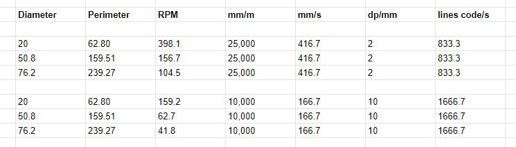
I think my expectations or off. As I understand now the GRBL has no idea what the A axis diameter is, so it will not adjust the rotary rpm to match the linear speed provided. Further larger diameters will have much more “dots” than smaller diameters.