Interesting that it states some lasers are stuck on no matter the S value in the Gcode with the default frequency of 5KHa(200 uS) and that sometimes 400uS period sometimes works to provide PWM control. It’s easy enough to try since it’s just changing the one entry in the config.txt file.
I did learn that Smoothie post processor uses 0.0-1.0 for the laser power settings. GRBL and LinuxCNC use 0-1000.
Since I was on the C3D web page I went to the forum and saw your post. I’d forgotten you had it connected up and it jogged and moved as expected AND it wasn’t automatically firing but when you tried to run a design it overloaded your breaker and from then on it would automatically fire the laser.
We know now that the C3D power supply powers the C3D board and it powers the stepper motors so the hissing sound you hear after you turn off your K40 is the stepper motors and not the laser tube.
As for the breaker being thrown, you had the 40W K40 which is 40W of output power so maybe more like an 80W draw on the circuit, rounded to 120W would mean 1A at 120V so not much. The C3D has a 24V 3A(?) power supply so that’s only 72W so even rounded up to 120W/1A is still only 2A so this should not have tripped a breaker unless it was already seriously over loaded.
SOMETHING else must have happened to cause the breaker to trip…
I also have to ask, when you install the M2Nano board and test fire it, how exactly do you do that? Have you installed K40 Whisperer or Meerkat to test fire it?
When a GFCI trips it means that there is an electron loss somewhere between hot and the neutral that feed the GFCI. Like if something is shorted and the hot sourced from the GFCI outlet is then sent to neutral on a different circuit, or ground, not necessarily an overload condition. Not saying it can’t be though. Don’t know if this helps.
right, he did say GFCI and for some reason I was just thinking breaker overload. Thanks for pointing that out. Still seems something shorted to cause the GFCI breaker to trip and then the C3D only would fire the laser when connected.
Still confused with how the M2Nano was being test fired.
Keep in mind the laser comes on with power on, a solid and basic problem with a control signal to the LPS.
It seems clear that the C3D is holding the L pin at a low enough point to fire the laser all the time. The question I have now is why?
There is no PWM signal from the C3D since a job is not running so doing anything with Gcode is not going to point us to the problem.
Clearly the GFI fault occurring just prior to the C3D’s current condition suggests a cause-effect. GFI breakers can trip with the smallest (4ma) of imbalance in the AC in and out.
There was some leakage from something that was plugged into that circuit and it could be the pump, K4 or the laserboard. Since the only change in AC devices between the Nano and C3D configurations, was the laserboards power supply I suspect it. It also seemed related to plugging in the USB cable which may have created some strange ground loop.
Since no breakers blew after moving them I assumed the leakage was not do to a short but some kind of smaller leakage.
Note: I have experienced poorly designed DC supplies with higher than normal leakage.
All, I distinctly remember hearing a hiss coming from the machine immediately after installing the c3d. I have read other threads about the LPS making that noise so I assumed that was it. I did not have any material in the bed at that time to see that it was the laser. I remember turning the power down to 0 and it stopped. Again, I assumed “okay, I have to turn the power up at least to the point where I start hearing this sound. That must be the lowest power setting for the laser to be able to fire.” Stupid, but hey, it was my first time powering it on.
I believe the GFI trip was due to the USB issue since I remember hearing the hiss prior. It was only after the breaker tripped that I looked closer into it being the laser firing.
I didn’t word it very well in that original post, like I said, I wasn’t able to differentiate between what I thought was the sound of the LPS and what I now know is the sound the laser makes when firing.
Long story short, I really don’t think the GFI caused the c3d to be placed into this state. It’s been doing it from the beginning, it just took me time to realize it.
Obviously I could be wrong, but I’m trying my best to think back and this is how I remember things happening.
I think the fact that I was getting the USB connection error before the GFI incident and now I don’t further supports the theory that the USB issue was the origin of the GFI incident.
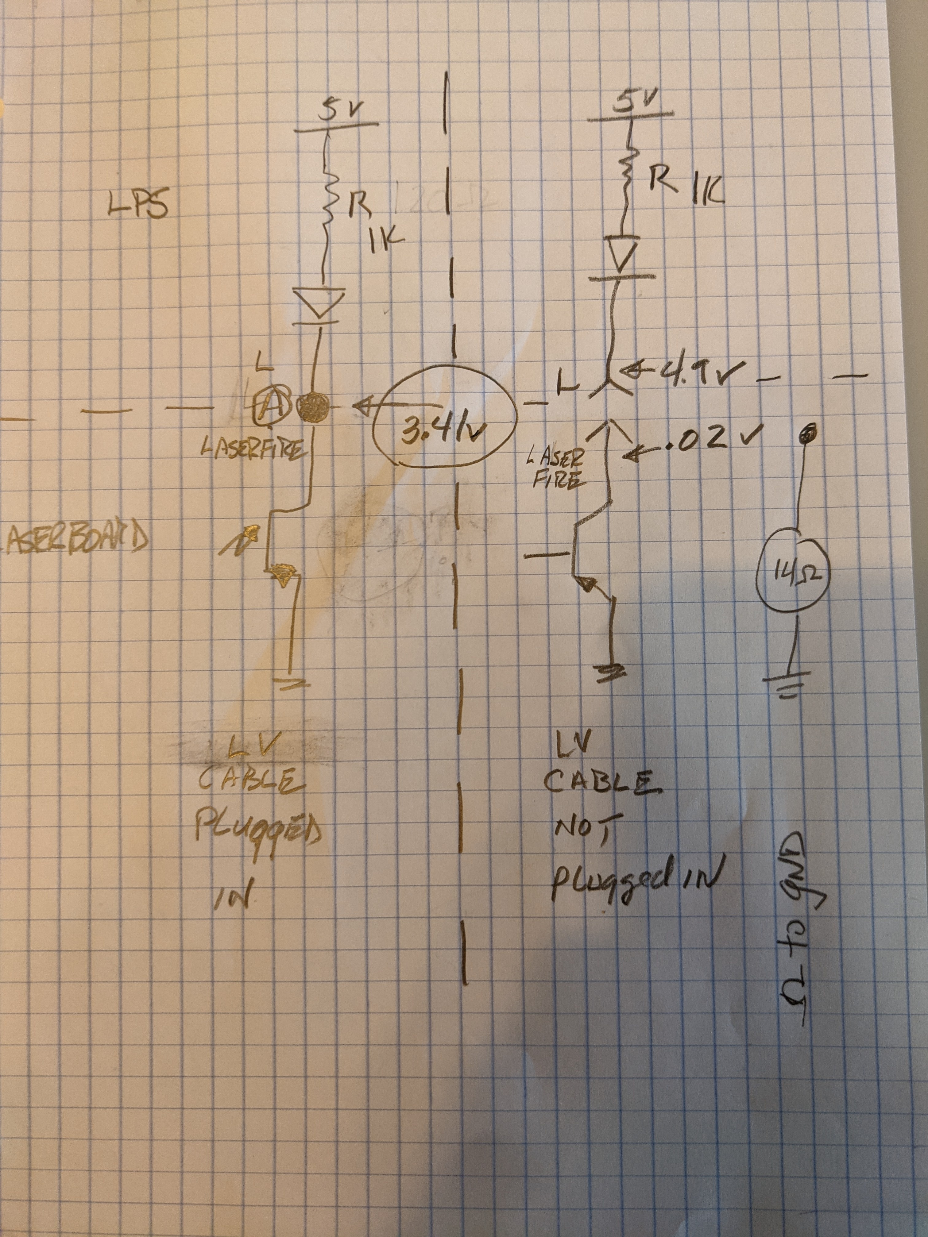
In the left circuit with the C3D inactive I would have expected the voltage at Laserfire to be close to 5V. Instead it was 3.41v which suggest to me that there is current flow even though the transistor in the C3D’s optocoupler should be off.
In the right circuit we see that disconnected the voltage reads .02 which is to be expected. However the resistance reading to ground was 17 ohms (drawing in error says 14). That transistor with no connection should read OPEN?
That said, the math to get 3.4V at the terminal would be larger than 14 ohms [more like 680]. Something else at play we don’t see. (Im ignoring this for a moment )**
Now I am thinking that the C3D’s output opto is bad.
Is this somehow related to the GFI incident … I don’t know. Note: that there is one identical case on the C3D forum where the Laserboard had a bad opto.
Before we proceed down the path of opto replacement:
Check me: is my analysis flawed or illogical in any way you can see?
Any other source of the problem or test you can imagine
Remeasure the resistance from Laserfire to ground
Make sure the Laserboard’s power supply is unplugged
Take two measurements: take a measurement, flip the leads and take a second one
We can desolder pin 4 on the opto and see if the laser still fires at power but that is the same as unplugging the cable.
**I measured the resistance to ground on the collector of an 817 and as expected it read open in both directions. Assumes a 217 output is similar to 817.
Dylan, these machines are a learning experience when everything works normally and we’ve all been down the road to one extent or the other. And still learning. My electronic theory is decades old and rusty, Don’s much better and this is a challenge to understand even moreso via remote control but it’ll be figured out and a solution defined.
We’re almost at a point were things are exposing themselves to the point of understanding.
I assume you mean the test fire on the control panel?
You can if you want but the laser is already firing at this point. It fires all the time so don’t see this adding any light to the case. Then again every hint is worth something.
Test fire comes from the panel by grounding K+. We already disconnected K+ with the LV connector installed and the laser still fired at power on.
FYI the K+ and L signal are connected together (same signal) inside the LPS so K+ or L can pull the line to ground and fire the laser.
@dougl I appreciate that. I am still excited about the machine, I just wasn’t expecting so much troubleshooting right out of the gate.
You and Don have been amazing and so helpful. The support from C3D leaves a lot to be desired though… I know they are short staffed so I am trying to understand that.
I have no better ideas at this point than to replace the opto?
I would start looking for a L217-E3 IC.
I think the # actually is ACP-217 and E13 is the ROHS compliance code. I dont know what -ROHS E13 is. I would need to know the manuf and find the data sheet.
However I do not think that the ROHS code will matter in this case.
Really long lead time
You might find them on amazon, ebay etc but I usually don’t cause I do not know the quality.
Perhaps an 817 will work but I would have to do research, let me know what you find.
Have you ever soldered surface mount before?
This repair is not to tough.
Surface mount devices have pads etched into the PCB and the IC is layed on the pcb and then soldered.
You need to fully solidify the solder on the chip legs but not overheat them as overheating them will also cause delamination. Use a small tip iron.
You can also easily delaminate the solder pad if you pull on the chip before the solder is fully molten.
Delaminating the solder pad from the PCB is not good!
Look at method # 2 in this video which suggest you score the pins until they part and then after removal of the IC un-solder and remove the pins from the pads.
Replacing is easy. Tin the empty pads if needed. Lay the new chip in the right orientation on the pads. I like to hold it with a tweezer. Heat the chips pin just enough for the solder to flow and apply more solder if needed. Careful not to bridge 2 pins with solder.
Check connections with ohm meter.
I would take a photo before, after the IC is removed and then after replacement
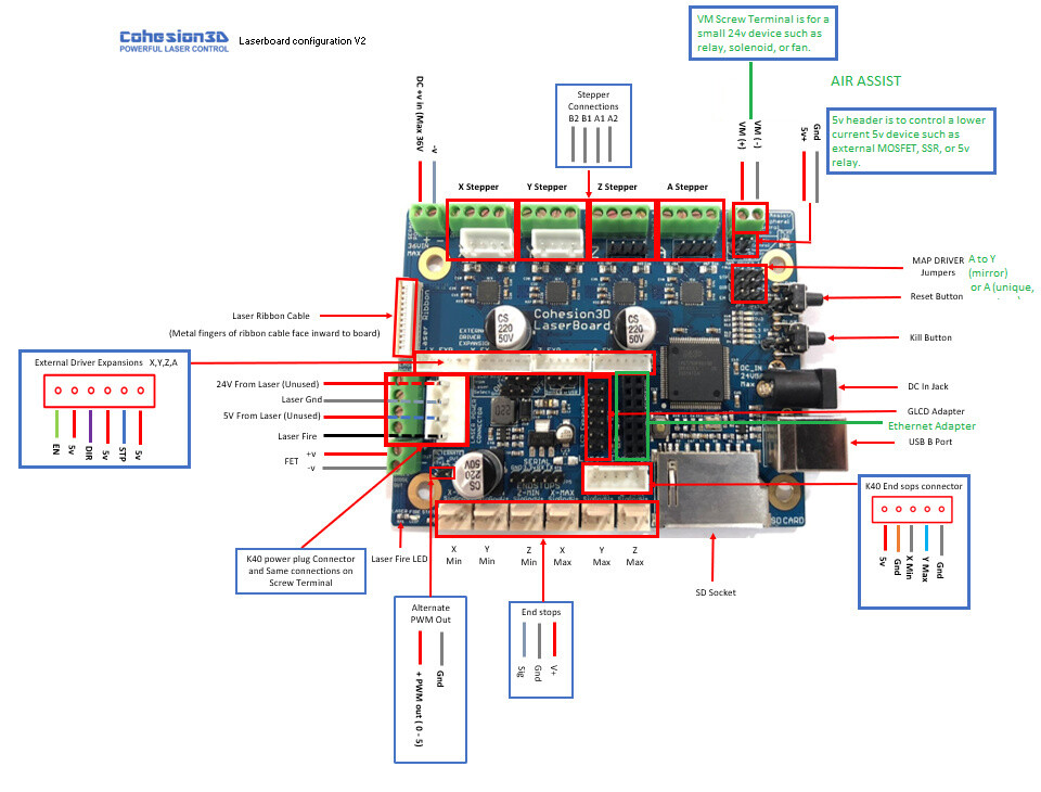
I just noticed that there is a Laserfire LED on the edge of the Laserboard on the corner just below the power supply connection.
Is this LED on when the laser is firing at power up???
Another option aside from replacing the Opto is to find an alternate open drain on the Laserboard that supports PWM and reconnect, remap (in config file) it to use to drive L.
Can’t find that part anywhere in stock. 20 week + lead time and then loads of shipping on top of that.
Is this really what it takes? Is there no way to get in touch with C3D? Seems to me they should be the ones supplying either a new board or replacement parts.
Ok this would suggest that the board is not asserting a signal (no led) yet the opto’s output is partially on.
Which is consistent with the opto being bad.