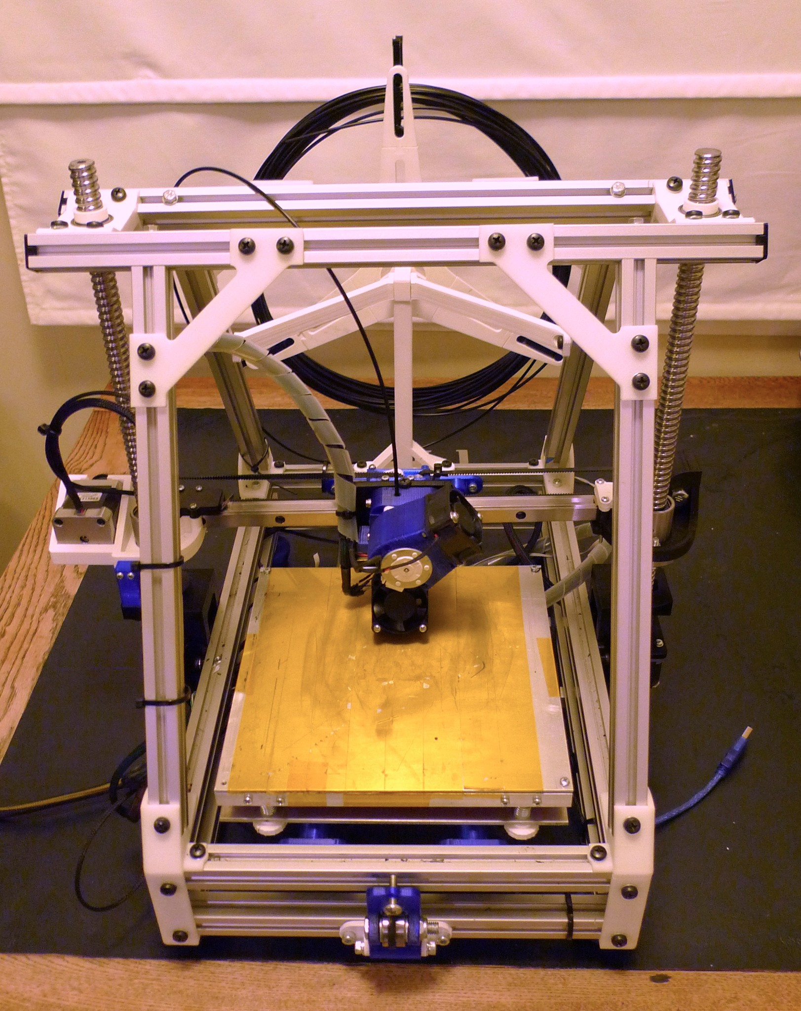
Mendelmax 1.5 with heavy duty Linear motion upgrades. CNC grade linear guide for the X, 16mm ball screws on Z (no guide rails) 12mm rod and CNC grade linear bearings on Y. All Z components, X ends and carriages custom designed. Been a bit of an adventure but the end result is very pleasing and super ridgid/smooth.


wow, that are some massive z-rods…is that better than smaller z rods with guide rails ?
Well, they don’t have much (any) flex :). Tbh, I didn’t set out to buy 16mm ball screws, I was after 12mm but the 16mm one’s were cheaper. Major plusses are less parts, high rigidity and extremely precise z movement.
Isn’t it overconstrained?
nice set up , i’m playing with 3 axis direct drive screws , driving both with the same stepper or is the right one out of sight ?
Nice! So how do the before/after prints compare? Have you thought about putting a milling end on there and trying some CNC?
The toolhead mount looks nowhere near capable of guiding a milling head. Even if it’s just for foam and wax.
would you mind telling me how much u got those ballscrew parts for? and where? how long is that overall?
i really wanted to put in ballscrews on my machine, then again after i saw the prices, i kinda flipped, cos my Z-axis is 1000mm 
You could get a lot more rigidity much cheaper by replacing all the joints in the frame that are common angles (so the 90 degree ones, i don’t think the bottoms of the triangle are quite 60) with proper metal joints. As is despite how tough those ball screws are it’s still probably not perfectly sturdy in X.
@Marcus_Wolschon overconstrained in what respect?
@Eric_Cha no more z axis artefacts I was getting from the axis screws I was using previously. Big difference is quality improvements for higher speed of prints. No intents for milling heads- too many plastic parts and wrong geometry I reckon.
@Nick_Parker plastic parts going when I upgrade the frame to a MM2.0 variant. (almost everything is 90 degrees then ). In saying that, you’re wrong that replacing the plastic would fix flex in x in the same way, the rods and lead screws I had previously had much more movement. With the ball screws, there is no perceptible movement when I attempt to move the x ends. Anyway, increased rigidity was only a secondary goal, primary was improved linear motion and it’s cheaper for me to source cnc parts from China than buy makerslides (or whatever) from the states.
@Marcus_Wolschon - Ah. I see. Well, how does that guy who made the Lego CNC do it? he’s milling foam… seems like if a cnc mill that was made from LEGO’s could do it, then Tim could do it as well… at least for foam… 
@Sanjay_Mortimer cheers :). Belt twist there as the belt teeth were binding on the cam that is part of the x tensioner and the MK1 design wasn’t strong enough to overcome the tension without the plastic failing. MK2 printed but not installed yet.
@Eric_Cha True enough. Sure this thing could handle foam if the milling head was fixed directly to the linear rails carriage. I don’t imagine the belts would like it much though, would have to go very slowly 
@3roomlab Sure, I’ll post links once I’m in front of my pc (too hard on mobile)
If you go slow, the foam melts and clogs the tool.
@Marcus_Wolschon Good point.
@Eric_Soulliage There’s a nema on each side. maybe when I upgrade to MM2.0 Frame design, I’ll look into single stepper option. It occurred to me you could mount a single nema at the top centre of the frame and use belts/pulleys to drive the screws. What sort of screws you using for your 3 axis? I’d guess you need something with a steep pitch to get a decent x-y speed. I’d looked at the 25mm pitch ones Trinity Labs sell but they are $100 each.
@3roomlab Here’s the links to those screws and the x linear guide:
http://www.aliexpress.com/item/Free-Shipping-1sets-SFU1605-Ball-screw-L350mm-Ballscrews-ballnut-for-CNC-XZY-NEW/714367567.html
Not sure how a ball screw only approach would work out with 1000mm Z though!