Originally shared by Sebastian Szafran
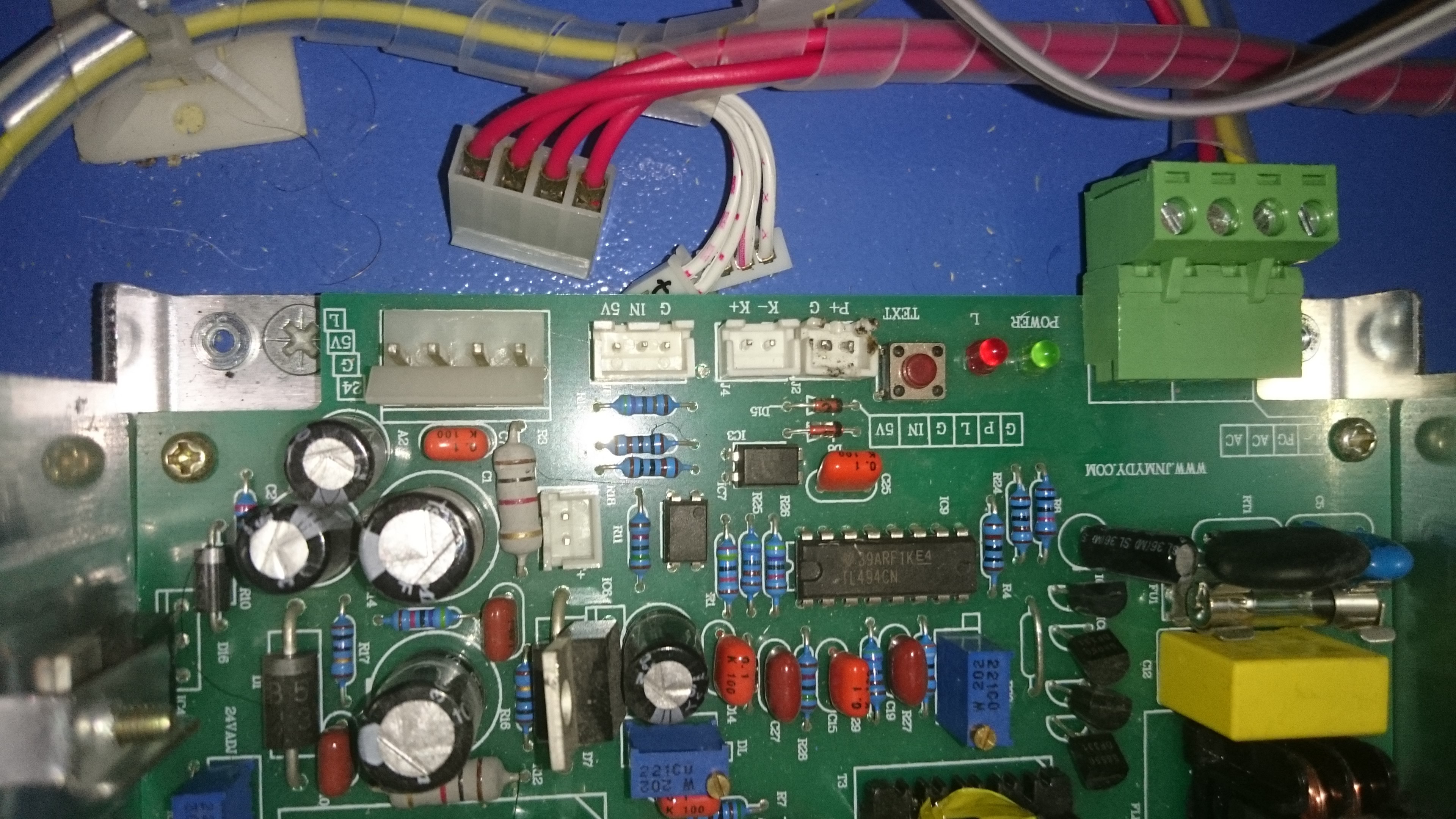
This is my K40 PSU. P+ and G has been bended and soldered by default. I unsoldered those pins to allow interlock switches (door, water flow, temperature sensors) connections.
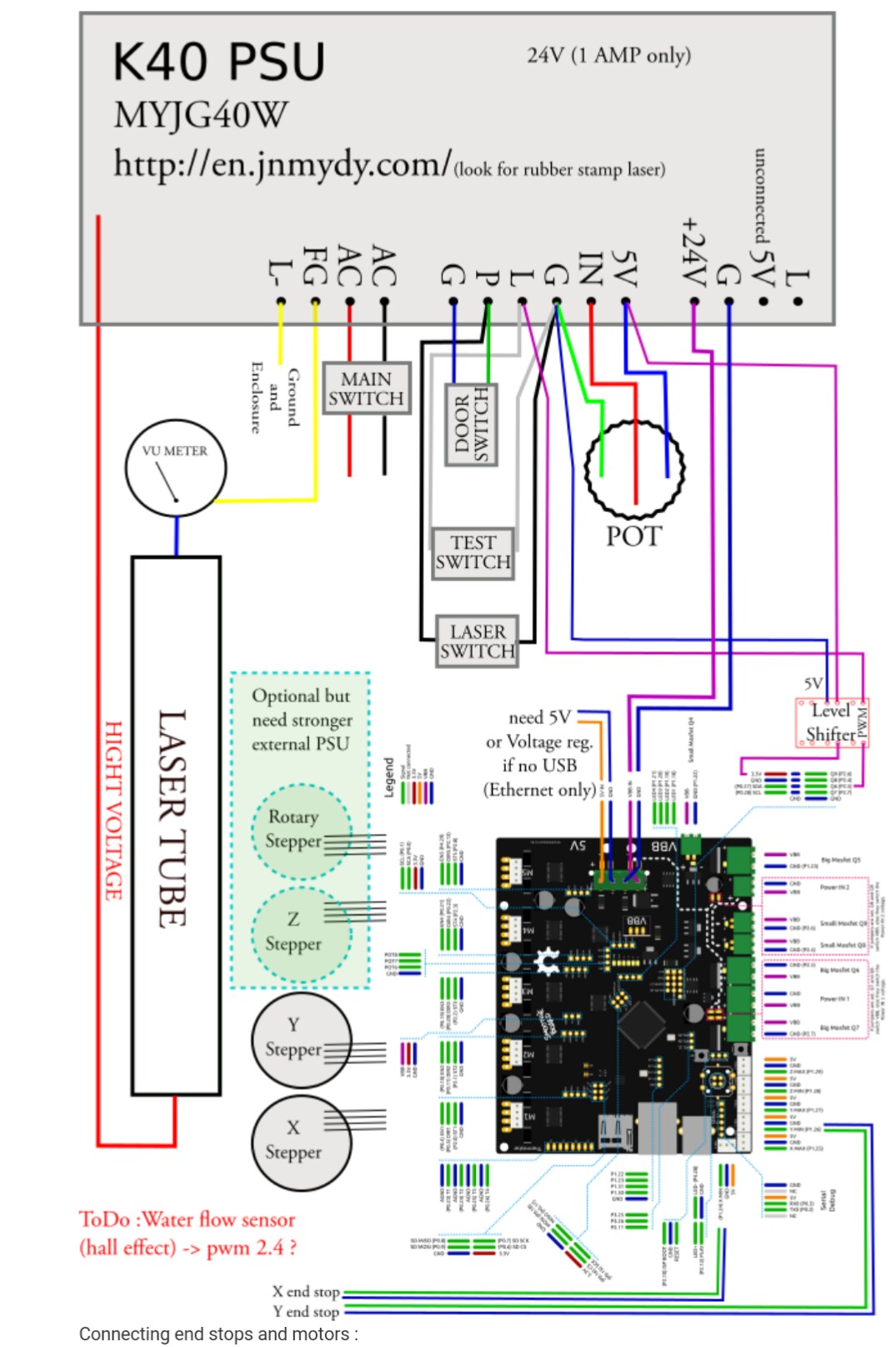
Based on the Smoothie conversion diagram (http://smoothieware.org/blue-box-guide) what is the best way to do the conversion:
- Does the diagram work in way that L current value will be ‘directed’ by Smoothie PWM while POT sets the maximum current (ceiling = 100% PWM) value for the laser tube?
or - Is it better to connect Smoothie PWM to IN and remove POT?
or - Smoothie PWM1 connected to IN and Smoothie PWM2 connected to L and directed separately?
or other possibilities?