Would this arrangement work for a system that clamps the hotend both at the upper level (like they are normaly mounted) and at the lower level (to prevent rotation around the upper insertion point)?
I am trying to get an alternative to the previous “barbecue sticks” arrangement I was showing some time ago (ex: https://photos.google.com/share/AF1QipPn3pWAGU646vTtzIOsRqdQi5RfZ1a82xJcya-TPEy8Tta_kG5o6hluz66R4GlonA?key=ZF9CdVNmblpvSXBJa0t0R1lNVXlTUTVpNjlGUkJB)
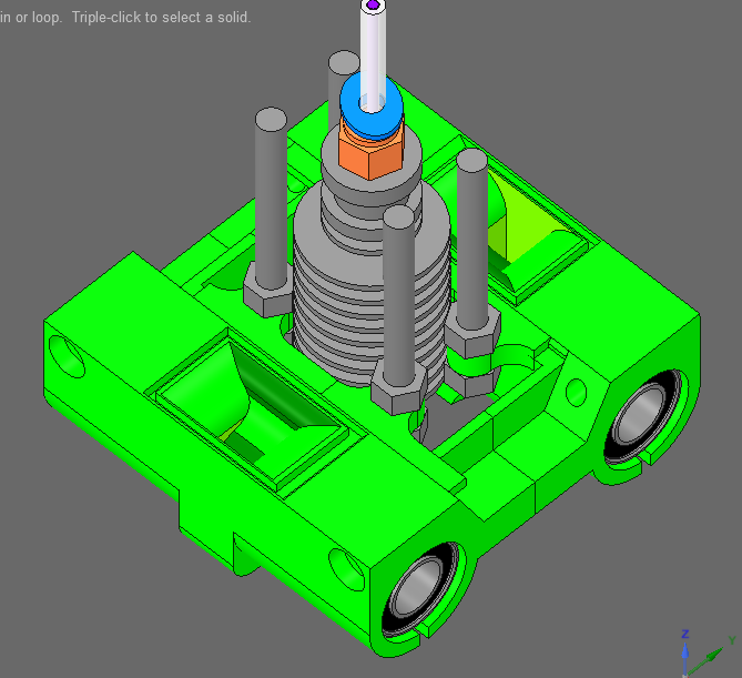
Basically there is an XCarriage eyelet that receives an M5 (M4?) bolt from underneath and screws into a nut on the upper side of the eyelet and of course there is a missing part, the actual hotend clamp that will come from above with the hotend and another set of nuts will set it in place (which I haven’t yet designed for I am not sure the eyelets can withstand the heat that the bolts will transfer from so close proximity to the hotend/lower fins).
Please let me know what you think.
Have you had trouble with the hot end rotating in the past? With an appropriately sized and tightly fastened mount I’ve never seen one that could rotate at all.
It’s usually a number of factors that end up being at fault for errors in prints and ruling them out could be a good way to solve them one by one. And I am quite a a big fan of the fully supported hotend for a most rigid structure because it’s mostly plastic and that is not rigid like metal would.
.
In the above configuration, the upper clamp must anyway have a vertical members arrangement to connect it to the base so having screws for that is also providing that function.
I just don’t know about the heat creep into the eyelet that lets the bolt through. The nuts will lay against the fins so the hotend would be supported laterally at the base.
Ok, gave up this design experiment because it’s not adjustable and the heat creep through the bolt would soften the eyelet and the metal parts will shift and the contact of the flats on the nuts to the hotend would be compromised without an adjusting mechanism…
Back to the drawing board.
Will be using a slight alteration of my previous design, with reversed hex-head bolts that lay their heads flat against the hotend fins -> https://is.gd/pS6KLi
@David_Sherwood
If you can show some pictures that’d be awesome. To be clear, are you talking about the arrangement in the post or about the (“set horizontally” would suggest the latter but I want to be sure)
Lol, that’s almost the same  … I use 4 bolts for design constrain and symmetry purposes and in the last iteration I have the bolt reversed, with the hex flat head pushing into the fins so I can cover 2 or 3 of them.
Thanks for chiming in, i’m actually glad someone else did this before.
I had it with in-between-fins screws initially but the fins are 2.15mm apart so I would have had to actually force it in or even thread that space for a VERY VERY constrained hotend but that is too much work, too long screws, etc… so ended up trying to lay a flat against the fins.
One question though: as this needs to be pretty rigid, are you running it through threads cut into the plastic or use some sort of nylock embedded nut to keep it from wiggling its way out of touch end negate the effect?