Hello. I have a problem to connect laser 80w with PWM signal to TTL on board MKS DLC32 v2.1. When connecting the laser to the TTL connector, it produces a maximum of 5v. How to make it give out all 12 volts of the PWM signal.
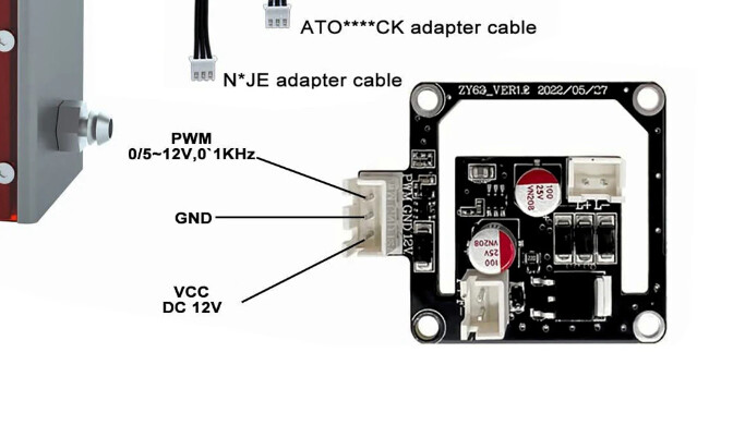
TTL means 0/5V, technically. This board appears to advertise also tolerating up to 12V.
It only puts out 5v.
That should not be a problem. That’s what TTL means.
The annotation says “PWM 0/5~12V” and 0/5V is TTL.
The fact that it can also tolerate 0-12V signalling is a bonus.
“all 12 volts of the PWM signal” doesn’t make sense, because TTL signalling is 0 for off and 5V for on.
Now I understand everything. Don’t need any extra board, just connect directly.
The MKS DLC32 has a specified maximum wattage of 25W@12V or 50W@24V. You laser exceeds what the board can supply off it’s V pin, current wise…
This is from the manual …

I suggest you use an interface board, but in any case your laser draws more current that can be safely run through the board… G and S are fine… you’ll have to deal with getting a separate power/line for V on the laser module.
The most simple way is an interface board that’s probably plug and pray… I ran wires to handle the extra current on mine when I upgraded it… but the board can’t allow enough current to flow through it.
The pwm isn’t a problem, just the supply current…
Good luck
