Yes a newbie mistake even though I new I need to add an algaecide. I will sort this over the next few days
Here are the pics:
Control panel. 2.25V is 15mA current. Ambient temp is 26C so hard to cool at the moment !! The switch is for the red dots which is the only internal connection to the +5v
Test shot showing 15mA max at 2.27V
I am going to do another alignment tomorrow using the guide from the site and will send pics
LPS. The only change I have done is connect Red Dots to +5v

The Laser Head including side air assist and red dots
The air assist pump. 80L/min
Let me know if there are any other pics you want in the meantime
It is useful to create a characteristic curve for your supply which is in the post below.
That info gives a sense of how well the supply is working and it also gives you a baseline as it wears.
Yes I did read this when I was trying to work out what exactly % power means as I am not replacing a digital panel. I have engraved this guide to my settings but I assumed 100% power in my case is the max current i.e. 15mA but this might be wrong.
Are you saying that the voltage will increase in time to give the same current and this is what I need to monitor?
No. The output current will decrease over time for the same setting on the LPS-IN which is the center pin on the POT. So over time at the 2.25 voltage, the current will be less than 15 ma.
Note at the pot’s max setting it provides 5V at the LPS-IN meaning that 2.5V is 50% of its range, yet 100% of where you should run it.
Ok understood. Many thanks to everyone today for their posts today. To sum up:
- I need to change the water and add algaecide which I have now ordered but will take a few days but this is unlikely to be the cause of poor cutting.
- So, I will re-check the mirror alignment using the site guide and send in the spot results.
- Is the air assist having a negative impact in some way? Is the fact I am using a side vent an issue? I can test these out. I had already ordered the Cloudray laser head with better quality mirror and lens before this so awaiting arrival. Should I replace the other two mirrors for the higher quality ones?
- I believe extraction is working fine in getting rid of smoke as the hose is short and the assisted fans seem to work well.
- I have done a number of ramp tests and confirmed the optimum height does seem to be around 50mm and I have printed a tool at this height. I have confirmed this is consistent across the bed.
- In the hot weather it has been hard to get much laser time even with 4L of ice in the water and I have stopped at around 22C. I understand much above that the tube will underperform and degrade. Is this correct?
- What would be the best material to start with; 2.5mm birch? If I get back to where I was this should be 1 pass at 15mA and 10mm/s then I can try 3mm MDF
- If I do all this again and it still does not cut, would I have to conclude that the tube is damaged in some way? Are there any other tests that might prove the real power of the laser tube?
I would minimize what you change until you get acceptable results from what you have. A stock K40 will perform well. Most upgrades are for enhanced abilities, reliability, and safety.
I would create the IN voltage vs tube current graph from 0-5V to see what the LPS is capable of. You should use short bursts when doing this test.
I suggest adding interlocks as soon as you get things working and in the meantime use protective eyewear.
You recommend testing all the way up to 5v on the control from the pot? Overdriving the tube, but in a short enough burst not to damage anything just to get data?
Yes, you should not damage the tube if you just pulse the supply, perhaps go to 4 volts and extrapolate the rest.
Ok I removed the limiting resistor and then produced a list of IN voltage vs tube current as follows in steps of 0.5V:
V ------ mA
0.5 ----- 4
1.0 ----- 8
1.5 ----- 11
2.0 ----- 14
2.5 ----- 16
3.0 ----- 19
3.5 ----- 22
4.0 ----- 24
4.5 ----- 26 (estimated)
5.0 ----- 28 (estimated)
I estimated the last 2 readings as advised. Plotting this as a graph looks fairly linear to me. I hope this is what you were looking for. I had hoped to also provide a new mirror alignment but I will do this and send it tomorrow.
Cooling issues aside, my experience has shown that some materials don’t cut, they ablate. I’ve tried cutting foam core plywood and that is a total waste of time. Same with cork. I have cut high quality 3mm birch plywood at least a thousand times - no problem. Like one other user suggested, go back and attempt to cut some birch plywood to see if the problem is the laser or the material. And rig up an air assist system system. It’ll clear the kerf as you cut.
I would say that the laser and LPS are in good shape.
The problem is probably in the optics.
MDF is much harder to cut then plywood because it has a much higher content of Urea-formaldehyde (UF) resin / glue. UF really doesn’t like to burn due to it’s high nitrogen content.
A good air assist can help some, but it’s not a huge help. In my experience, cutting MDF with a K40 laser requires slow speed, higher power and multiple passes.
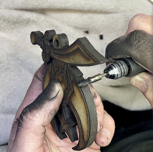
You’ll also ended up the a very chard edge. I’ve found using a plastic bristle bush in a rotary tool to grind off the char the works the best for char removal. It’s a bit messy and I strongly suggest wearing a good dust mask.
Yes I have gone back to first principles and I need to get it to cut 2.5mm birch ply first which it did do early last week
Yes I am just concentrating on getting to a position where I can cut 2.5mm birch ply again which was without air assist then I can move forward. Whereas it was flaming before air assist does seem to work well so not sure what the problem is so trying to re-align the mirrors again.
My comment about air assist was more about trying to improve the air assist for cutting MDF. I tried adding a secondary close high pressure directed stream of air from an air pump and did seem to help much with cutting MDF.
Air assist is a definite must to prevent flame ups and does help with most cutting. ![]()
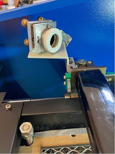
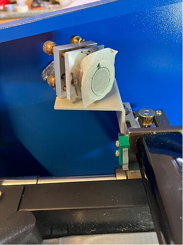
That’s good to know. As the last few times I have aligned the mirrors, they were not perfect but good enough to cut 2.5mm birch ply, I did want to do a proper job this time and used the guide from the site. Using tape sort of works ok if it is only you looking at the results but indenting where the hole is is iffy at best with the fixed mirror with its confined space so I produced a jig which goes over the mirror cover
and stick the tape to that so there is a clear centre of circle to aim at.
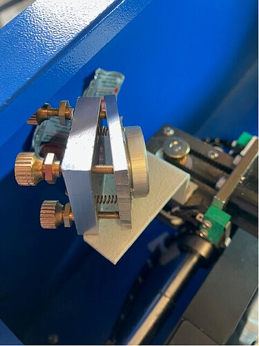
From this I did have to move the fixed mirror back so ok so far. I got a reasonable result hitting the Y stage mirror which presumably means the beam is running true down the Y axis but I noted I seem to have a problem with aligning the Y axis mirror X stage mirror which tracks horizontally as you move from A to B as it has run out of adjustment.
As you can see I would not expect the adjuster to be so angled and both screws have run out of adjustment. Is maybe the gantry not true as the bracket does seem to in line with where is should be or is it that I need to move the bracket which only has adjustment to move into cabinet? The horizontal is the issue not so much the vertical. I did not think it was worth continuing until you had time to comment.
Hard to tell but with the jig in place does the tape sit proud of the actual mirror surface?
Could that be affecting the alignment?
If the mirror alignment instructions tell you to put tape over the mirror I sure hope it also tells you to NOT burn through the tape. I repeat, do not burn through the tape. It will splatter hot glue onto your mirrors and make it very difficult to clean off. One trick others have used is to stick a coin on the other side of the tape to keep the glue from getting to the mirror.
And as Don mentioned, you are not looking to get the burn mark on the middle of the outside surface of the tape, you want the middle of the mirror and since the mirror is many mm behind the tape you’ll want the mark on the tape towards the high side of the mirror edge.
No this was a problem before I did so. The issue is only the horizontal not the vertical. My logic says that if A and B spots are generally tracking ok from the fixed mirror to the Y mirror the beam must be running correctly down the Y axis, so when it bounces off the Y mirror then the adjustable part of the Y mirror ought to be roughly in parallel with the fixed part i.e. 45 degrees so sending the beam 90 degrees across the gantry unless the gantry is not square or maybe I need to move the Y mirror assembly. As it is, the spots on the X mirror are not far off but I have run out of adjustment on the Y axis with B and C screws at the end of their travel in one direction and the A screw in the other. No doubt I will figure this out but I sense optics is the problem as you said this morning.


