…also
You do not need to call pinMode() to set the pin as an output before calling analogWrite() .
I have never done so therefore I don’t know if declaring it causes a problem.
…also
You do not need to call pinMode() to set the pin as an output before calling analogWrite() .
I have never done so therefore I don’t know if declaring it causes a problem.
I did comment out the pinMode() call on the analog pin early on.
My schematic is this:
Originally, I also had power running to the encoder circuit, but I disconnected that until I could figure out what was happening with the motor.
I think the most likely culprit is poor wiring. I am going to mount all the parts and redo it again, so I’m not carrying a jungle of wires around. I’m finally getting the JST connectors right, and some of the wire I got is really crappy. Things keep breaking and coming loose. II have actually really struggled with the screw terminals, especially the (-) where I have to secure two wires!
I’ll check back. I’ll also test the pwm output with my multi-meter.
One more question: what sort of interface should I set the teensy to, in order to get console messages? Serial? I’ve only ever used MIDI…
Just a guess but maybe when you removed the 9V battery you also removed the groundwire from the connector over to the Arduino/Teensy? Or maybe that wire is flaky and since you are carrying more current over that ground I would include a 2nd ground wire as those jumper wires are usually very small gauge wire.
well, I should also mention that instead of a 9v battery I have a 12 volt 400ma ps with a jack and plug.
Ahh… I did not realize that at all!! So I’ll need to pull 5v via DC/DC from the PS when it comes time to run without USB connected. Does the 5v pin on the teensy function as an output when it gets USB power? And as an Input when not USB powered? I realize that’s what I was thinking, but now I’m not sure that is necessarily correct…
Okay, then, here’s how I plan to wire:
Power:
12vPS + to 298
12vPS ground to 298 and on to teensy.
5v from 298 - not connected, usb for teensy power. (It seems the teensy gets usb power even if it isn’t recognized by the computer as a usb device…) EDIT: I guess I could use the usb jack just to carry power. Hadn’t thought of that…
Control:
teensy digital outputs to 298 M1 and M2 inputs.
teensy pwm output to 298 m1enable input.
encoder 5v and ground, from teensy 5v and gnd. I guess this 5v could come from the 298 instead. Any reason to prefer one over the other?
encoder out1, out2 to teensy digital inputs.
I’m not sure that the 5v on the 298 breakout can provide the current that the teensy needs. I think it’s intended as a logic level reference not a supply.
It would be helpful to have a schematic that matches exactly how it’s currently wired  including the power connections.
What jumpers are on the Hswitch module and what position are they in?
Also, can you post close up picture(s) of the L298 module you are using.
One showing the top side
and
One showing the bottom side
If this is like other modules “if the jumper is set right” the 5V capacity should be about 1 amp.
This is probably not exactly the right schematic.
Well, I think I let the magic smoke out of the teensy LC with all my bad wiring… So I’ll get back with you when a new one comes. Glad these are cheap.
However, I will put some info here anyway. Here’s the specs for my h-bridge:
"
Driver chip: L298N dual H-bridge driver
Drive Voltage: +5V to +35V (Input voltage must be at least 6V when internal 5V regulator is enabled)
Drive peak current Io: 2A / Bridge
Logic power supply range Vss : +4V to +5.5V DC (Not required when internal regulator is enabled. When enabled, the 5V is available as an output on the power connector
Control signal input voltage range: 4.5-5.5V high 0V low
Maximum power consumption: 20W
Storage temperature: -25 ~ +130 C
Dimensions (approx): 43mm x 43mm x 27mm LxWxH (1.7" x 1.7" x 1.1")
Weight: 26g
The module includes an onboard 5V regulator. When enabled by the jumper, the 5V is provided as an output on the power connector, and can be used as a 5V DC supply for your other circuit components. (When enabled, the module input voltage must be at least 6V). When disabled, a separate 5V input provides in order to control the logic level circuitry of this module."
I left the jumper on, which means it could have run the teensy, correct?
Here’s the link… https://www.amazon.com/gp/product/B07NKJFTGM/
I’ll get a photo of the back…
@donkjr is right, I was wrong. Yes I’d expect that to be able to drive the teensy. However, I wouldn’t use that in practice because it sure looks like a linear regulator. I’d be using a buck convertor to bring the voltage down to 5V.
I’m assuming you are using the Teensy LC for this. Note that the pin labeled “5V” on the board is “Vin (3.7 to 5.5 volts)” on the pinout diagram
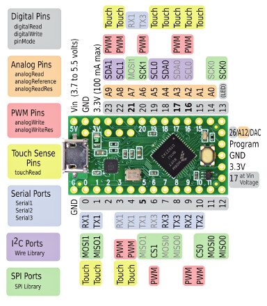
It’s not so much “output” or “input”. It’s nominally 5 volts; it’s connected to the +5V power bus on the teensy which is also connected to the +5V line from the USB connector. What direction current will flow depends on the exact voltage. It can be used to supply the Teensy, and it can be used to supply 5V from the Teensy to other components if the Teensy is USB-powered; PJRC gives the example of using it to power neopixel LEDs. I don’t know whether the teensy has any protection from sending current back down the +5V USB line to your computer, I don’t see schematic or specification about whether there is a diode there. But I wouldn’t put a 5V power supply and USB power both at the same time without knowing it’s safe.
Also along the lines of agreeing with @donkjr:
You’ve just signed up for easyeda, why not use that to draw a schematic of what you intend to wire? It really helps avoid wiring mistakes to have a written plan first, and you can share the schematic here. If you do that, please provide screenshots to make it easy to read directly on the forum. ![]()
Motor Driver Modules
I don’t think there would be a problem with running the teensy from the motor control 5v. Its linear regulator is a 7805 which is a pretty universally applied part for its application. That is if the load is less than 1A. [could be 1.5A depending on the version of the 7805]. This would have the advantage of not having to run 12 & 5V to each channel?
When I build something like this I like to isolate and verify each module is working before connecting the processor. I would hook up the motor controller, jumper its inputs and verify that it works and then connect the processor and firmware. Just verify the controller runs the motors forward and back without PWM control.
Teensy Power configuration:
It looks like there is a jumper [on bottom] to isolate the VIN and USB power?
“A pair of pads are linked to join VUSB to VIN. For applications where external power is needed, these pads may be cut apart to isolate the board’s VIN power from VUSB.”
The schematic also shows a fuse on the board so you might want to check if it is blown
well at one point I had the motor going both ways under teensy control, so I think the 298 board is working. I think I just had the power connected wrong, because it only was bi-directional when the external supply was disconnected. Then it seemed like power from the teensy was running the 298, which I don’t think is recommended. The motor was slow and weak, but it did reverse.
If that fuse is smd, I’ll put the teensy in my parts bin, and maybe try to resurrect it some other time. A new one will be here tomorrow.
Great idea. I have a basic working concept of a schematic, but having an app to guide me through creating a proper one seems like a good means of getting up to speed. I’ll try and do that today. I re-did all the wiring last night with good wire, and mounted all the components on my one-string test guitar. So I have a clear sense of where everything should go–except 5v!
I need to go look up ‘buck converter’. When I read that I thought you just meant it was cheap ![]() Some of them are only a buck, though. I’m assuming if I get a good one, I’d only need one for all 8 strings? Looks like t\he cheap ones overheat with higher current.
Some of them are only a buck, though. I’m assuming if I get a good one, I’d only need one for all 8 strings? Looks like t\he cheap ones overheat with higher current.
IMO, I still don’t see a problem with running the teensy from the 5V out of the motor control board. Then you only need one 12V supply that can handle the current drawn by the whole guitar.
Buck converters (I chuckled at your $1 perspective) can be more efficient but they also can be noisy, especially the cheap ones. I do not think the Teensy is drawing enough current for there to be a heat problem with the linear regulator.
If you have the 5 jumper installed on the motor driver module and the 5V IN on the Teensy isolated from the USB power [removing its jumper] then I think you are ok.
yeah, there’s the rub…
Should be good for the 1-string test unit. Before building a full guitar, I would like to move to Frank Hermann’s solution here: https://www.youtube.com/watch?v=0IbSE-sqBWQ&t=342s --but I’m going to want to redesign the circuit boards to 10x14mm instead of 12x12, so I can fit them in a 10.5mm string spacing array. I edited the component positions, but figuring out the PCB traces is going to take some study! However, I’ll be starting the process of getting up to speed by drawing my current schematic on the site…
What is “the rub”?
I was thinking of the fact that these could run up to 36V and 1A dropping 31V is hot. But you are right the Teensy isn’t really going to draw that much. Ultimately if it’s too hot that can be a later change.
I am used to putting a LDO behind a buck converter to take the noise out, without giving off lots of heat. But that makes sense to be a later refinement if needed, no point in doing it if not!
I didn’t break the connection… you are supposed to cut through the trace on the board to run the teensy from non-usb power. I assumed that had something to do with frying the teensy, but I don’t know that…
Are you sure the motor encoder VCC is 5V and not 3.3V? Mine are 3.3V.
Looks like both are okay…
" Encoder wiring method:
Red → motor power + (exchange can control the motor positive and negative)

Black → coded power + (can not be wrong with positive and negative levels 3.3-5V)

Yellow → signal feedback (7 signals per turn)

Green → signal feedback (7 signals per turn)

Blue → Encoder Power Supply - (Positive or negative can not be wrong 3.3-5V)

White→Motor power supply - (Transposition can control the motor forward and reverse)
"
not sure what is meant by ‘can not’. ‘Must not?’ or the opposite? I’m thinking the opposite, but not sure. I did get the pins in the wrong order on the schematic though…
oh, yours is actually the one I referred to when I originally started wiring… then I couldn’t find it again 
I had thought it would be 5v, because it’s a power input, not a logic input… but sounds like that is not a solid rule.


